Removal / installation · Vehicles built from Nov 2012
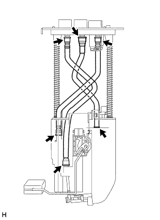
NOTICE:
Do not disconnect the hoses indicated in the illustration.
1.
REMOVE FUEL SENDER GAUGE ASSEMBLY
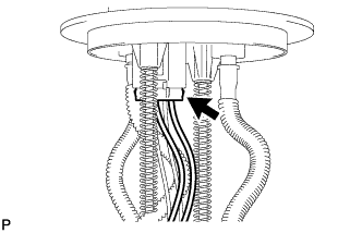
Disconnect the fuel sender gauge assembly connector.
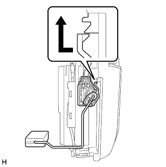
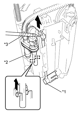
As shown in the illustration, disengage the lock of the claw, slide the claw upwards, and remove the fuel sender gauge assembly from the No. 1 fuel sub tank.
2.
REMOVE NO. 1 FUEL SUB-TANK
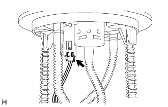
Disconnect the fuel pump connector.
Disconnect the jet pump A from the No. 1 fuel sub-tank.
Text in Illustration
*1
Jet Pump A
*2
Jet Pump B
*3
Protective tape
Using a screwdriver with its tip wrapped in protective tape, disengage the 2 clamps and the claw and disconnect the jet pump B from the No. 1 fuel sub-tank.
NOTICE:
Do not damage the No. 1 fuel sub-tank.
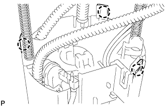
Disengage the 3 claws.
NOTICE:
Do not damage the No. 1 fuel sub-tank.
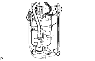
Disengage the 3 claws and remove the No. 1 fuel sub-tank from the fuel filter case.
NOTICE:
Do not damage the No. 1 fuel sub-tank.
3.
REMOVE FUEL PUMP WITH FILTER ASSEMBLY
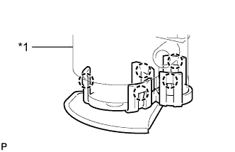
Disengage the 5 claws and separate the fuel pump with filter assembly from the fuel filter case.
Text in Illustration
*1
Fuel Filter Case
Disconnect the fuel pump wire harness connector from the fuel pump with filter assembly to remove the fuel pump wire harness.
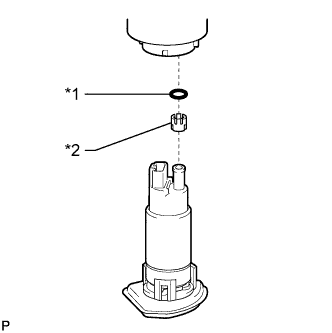
Remove the O-ring and fuel pump spacer from the fuel pump with filter assembly.
Text in Illustration
*1
O-Ring
*2
Fuel Pump Spacer
4.
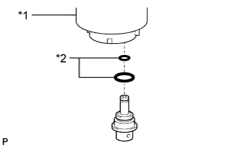
REMOVE FUEL MAIN VALVE ASSEMBLY
Remove the fuel main valve assembly from the fuel filter case.
Text in Illustration
*1
Fuel Filter Case
*2
O-Ring
Remove the 2 O-rings from the fuel main valve assembly.