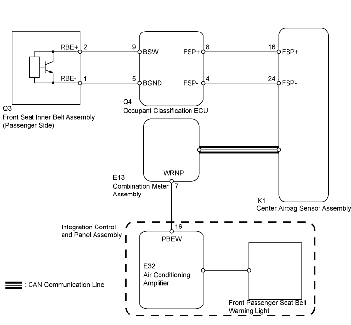
SEAT BELT WARNING SYSTEM > Front Passenger Side Seat Belt Warning Light Malfunction |
| 1.CHECK DTC OUTPUT (CAN COMMUNICATION SYSTEM) |
Clear the DTC.
Recheck for DTCs.
| Result | Proceed to |
| DTC is not output | A |
| DTC is output | B |
|
| ||||
| A | |
 |
| 2.CHECK DTC OUTPUT (AIRBAG SYSTEM) |
Clear the DTC.
Recheck for DTCs.
| Result | Proceed to |
| DTC is not output | A |
| DTC is output | B |
|
| ||||
| A | |
|
| 3.CHECK DTC OUTPUT (OCCUPANT CLASSIFICATION SYSTEM) |
Clear the DTC.
Recheck for DTCs.
| Result | Proceed to |
| DTC is not output | A |
| DTC is output | B |
|
| ||||
| A | |
|
| 4.CHECK HARNESS AND CONNECTOR (COMBINATION METER ASSEMBLY - AIR CONDITIONING AMPLIFIER) |
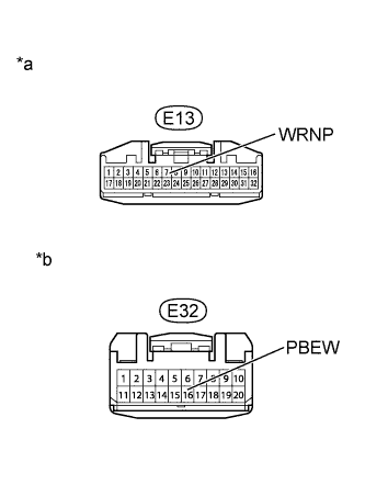 |
| *a | Front view of wire harness connector (to Combination Meter Assembly) |
| *b | Front view of wire harness connector (to Air Conditioning Amplifier Assembly) |
Disconnect the E13 combination meter assembly connector.
Disconnect the E32 air conditioning amplifier connector.
Measure the resistance according to the value(s) in the table below.
| Tester Connection | Specified Condition |
| E13-7 (WRNP) - E32-16 (PBEW) | Below 1 Ω |
| E13-7 (WRNP) or E32-16 (PBEW) - Body ground | 10 kΩ or higher |
Reconnect the combination meter assembly connector.
Reconnect the air conditioning amplifier connector.
|
| ||||
| OK | |
|
| 5.INSPECT COMBINATION METER ASSEMBLY |
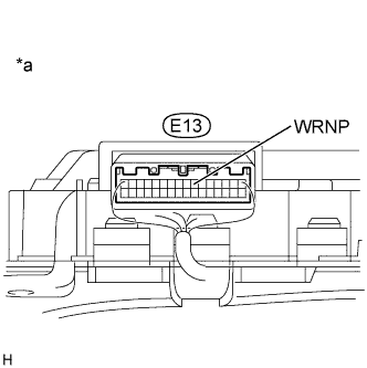 |
| *a | Rear view of wire harness connector (to Combination Meter Assembly) |
Measure the voltage according to the value(s) in the table below.
| Tester Connection | Condition | Specified Condition |
| E13-7 (WRNP) - Body ground | Ignition switch ON Front passenger seat occupied | Alternating between 11 to 14 V and below 3 V |
|
| ||||
| OK | ||
 | ||
| ||
