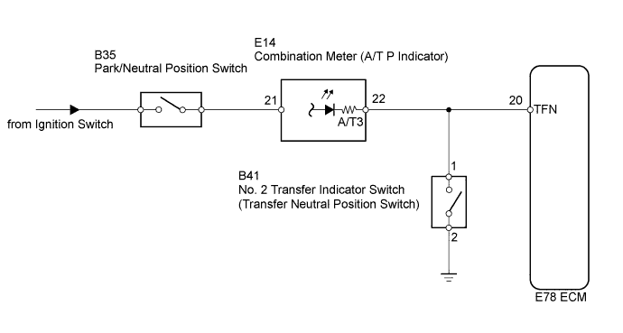
DTC P0818 Driveline Disconnect Switch Input Circuit |
| DTC No. | DTC Detection Conditions | Trouble Area |
| P0818 | No. 2 transfer indicator switch remains ON while vehicle is running under following conditions for 30 seconds. (2 trip detection logic):
|
|
| Related DTCs | P0818: Transfer neutral position switch/Verify switch cycling |
| Required sensors/Components | No. 2 transfer indicator switch (Transfer neutral position switch), Vehicle speed sensor |
| Frequency of operation | Continuous |
| Duration | 30 seconds |
| MIL operation | 2 driving cycles |
| Sequence of operation | None |
| The monitor will run whenever the following DTCs are not present. | None |
| Vehicle speed | 25.1 km/h (15.6 mph) or more |
| Transfer position | High |
| Ignition switch | ON |
| Battery voltage | 8 V or more |
| Starter | OFF |
| Transfer neutral position switch | ON |
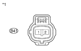
| 1.CHECK HARNESS AND CONNECTOR (NO. 2 TRANSFER INDICATOR SWITCH - BODY GROUND) |
 |
Disconnect the E78 ECM connector.
Disconnect the B41 No. 2 transfer indicator switch connector.
Measure the resistance according to the value(s) in the table below.
| Transfer Connection | Condition | Specified Condition |
| B41-1 - Body ground | Always | 10 kΩ or higher |
| *1 | Front view of wire harness connector: (to No. 2 Transfer Indicator Switch) |
|
| ||||
| OK | |
 |
| 2.INSPECT NO. 2 TRANSFER INDICATOR SWITCH (TRANSFER NEUTRAL POSITION SWITCH) |
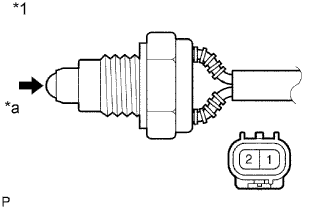 |
Remove the No. 2 transfer indicator switch.
Measure the resistance according to the value(s) in the table below.
| Tester Connection | Switch Condition | Specified Condition |
| 1 - 2 | Switch ball is pushed | Below 1 Ω |
| Switch ball is not pushed | 10 kΩ or higher |
| *1 | Component without harness connected: (No. 2 Transfer Indicator Switch) |
| *a | Push |
|
| ||||
| OK | ||
 | ||
| ||
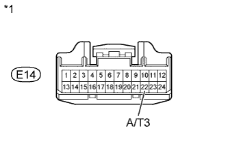
| 3.CHECK HARNESS AND CONNECTOR (COMBINATION METER - BODY GROUND) |
Disconnect the E14 combination meter connector.
 |
Measure the resistance according to the value(s) in the table below.
| Transfer Connection | Condition | Specified Condition |
| E14-22 (A/T3) - Body ground | Always | 10 kΩ or higher |
| *1 | Front view of wire harness connector: (to Combination Meter) |
|
| ||||
| OK | ||
| ||
| ||

