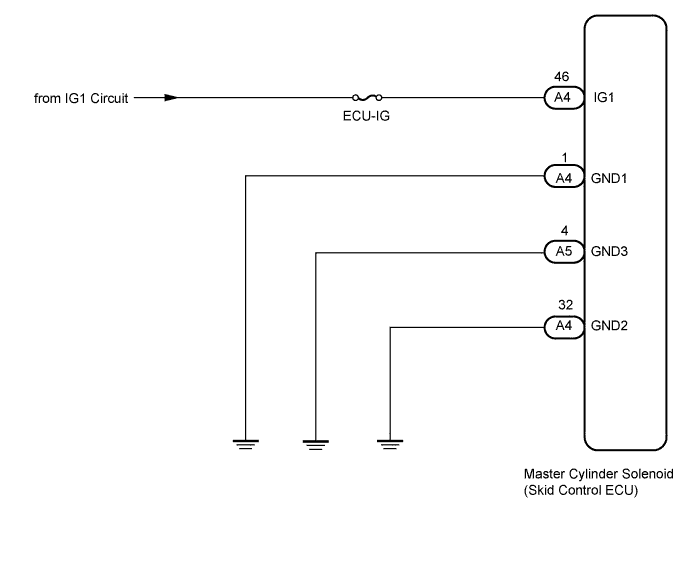
DTC C1241 Low Power Supply Voltage Malfunction |
| DTC Code | DTC Detection Condition | Trouble Area |
| C1241 | When either of following conditions detected: 1. Both of following conditions continue for at least 10 seconds.
|
|
| 1.READ VALUE USING TECHSTREAM (IG VOLTAGE) |
Turn the ignition switch off.
Connect the Techstream to the DLC3.
Turn the ignition switch to ON.
Turn the Techstream on.
Start the engine.
Enter the following menus: Chassis / ABS/VSC/TRAC / Data List.
| Tester Display | Measurement Item : Range | Normal Condition | Diagnostic Note |
| IG1 Voltage Value | IG1 voltage value/ Min.: 0.00 V, Max.: 20.00 V | 11 to 14 V | Changes in proportion to battery voltage |
Measure the voltage output from the ECU displayed on the Techstream.
| Result | Proceed |
| Data display is within Normal Condition | A |
| Data display is not within Normal Condition | B |
|
| ||||
| A | |
 |
| 2.RECONFIRM DTC |
Clear the DTCs (Click here).
Turn the ignition switch off.
Check if the same DTCs are output (Click here).
| Result | Proceed to |
| DTC is output | A |
| DTC is not output (When troubleshooting in accordance with Diagnostic Trouble Code Chart) | B |
| DTC is not output (When troubleshooting in accordance with Problem Symptoms Table) | C |
|
| ||||
|
| ||||
| A | ||
 | ||
| ||
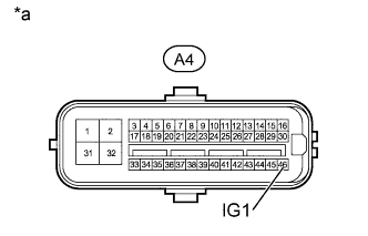
| 3.INSPECT SKID CONTROL ECU (IG1 TERMINAL) |
 |
Disconnect the skid control ECU connector.
Measure the voltage according to the value(s) in the table below.
| Tester Connection | Switch Condition | Specified Condition |
| A4-46 (IG1) - Body ground | Ignition switch ON | 11 to 14 V |
| *a | Front view of wire harness connector (to Skid Control ECU) |
|
| ||||
| OK | |
|
| 4.INSPECT SKID CONTROL ECU (GND TERMINAL) |
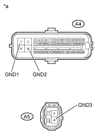 |
Measure the resistance according to the value(s) in the table below.
| Tester Connection | Condition | Specified Condition |
| A4-1 (GND1) - Body ground | Always | Below 1 Ω |
| A4-32 (GND2) - Body ground | Always | Below 1 Ω |
| A5-4 (GND3) - Body ground | Always | Below 1 Ω |
| *a | Front view of wire harness connector (to Skid Control ECU) |
|
| ||||
| OK | |
|
| 5.RECONFIRM DTC |
Clear the DTCs (Click here).
Turn the ignition switch off.
Check if the same DTCs are output (Click here).
| Result | Proceed to |
| DTC is output | A |
| DTC is not output (When troubleshooting in accordance with Diagnostic Trouble Code Chart) | B |
| DTC is not output (When troubleshooting in accordance with Problem Symptoms Table) | C |
|
| ||||
|
| ||||
| A | ||
| ||
| ||

