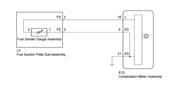
DTC B1500 Fuel Sender Open Detected |
| DTC Code | DTC Detection Condition | Trouble Area |
| B1500 | When combination meter detects fuel sender gauge assembly malfunction |
|
| 1.INSPECT FUEL SENDER GAUGE ASSEMBLY |
Remove the fuel sender gauge assembly (Click here).
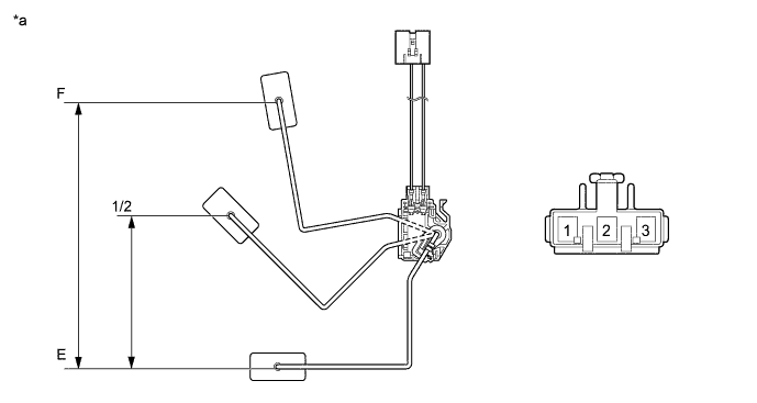
| *a | Component without harness connected (Fuel Sender Gauge Assembly) | - | - |
Check that the float moves smoothly between E and F.
Measure the resistance according to the value(s) in the table below.
| Tester Connection | Float Level | Float Position (mm (in.)) | Specified Condition |
| 1 - 2 | F | 174.9 to 180.9 (6.886 to 7.122) | 13.5 to 16.5 Ω |
| 1/2 | 95.6 to 101.6 (3.764 to 4) | 208.7 to 216.3 Ω | |
| E | 0 (0) | 405.5 to 414.5 Ω |
Reinstall the fuel sender gauge assembly.
|
| ||||
| OK | |
 |
| 2.INSPECT FUEL SUCTION PLATE SUB-ASSEMBLY |
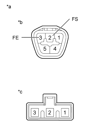 |
Remove the fuel suction plate sub-assembly (Click here).
Measure the resistance according to the value(s) in the table below.
| Tester Connection | Condition | Specified Condition |
| A-2 (FS) - B-2 | Always | Below 1 Ω |
| A-3 (FE) - B-1 | Always | Below 1 Ω |
| *a | Component without harness connected (Fuel Suction Plate Sub-assembly) |
| *b | Connector A |
| *c | Connector B |
Reinstall the fuel suction plate sub-assembly.
|
| ||||
| OK | |
|
| 3.CHECK HARNESS AND CONNECTOR (COMBINATION METER ASSEMBLY - FUEL SUCTION PLATE SUB-ASSEMBLY) |
Disconnect the E13 combination meter assembly connector.
Disconnect the L5 fuel suction plate sub-assembly connector.
Measure the resistance according to the value(s) in the table below.
| Tester Connection | Condition | Specified Condition |
| E13-16 (L) - L5-2 (FS) | Always | Below 1 Ω |
| E13-16 (L) - Body ground | Always | 10 kΩ or higher |
| E13-5 (E3) - L5-3 (FE) | Always | Below 1 Ω |
| E13-5 (E3) - Body ground | Always | 10 kΩ or higher |
| E13-21 (ES) - Body ground | Always | Below 1 Ω |
Reconnect the fuel suction plate sub-assembly connector.
Reconnect the combination meter assembly connector.
|
| ||||
| OK | ||
 | ||
| ||
