 |
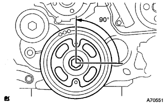
Set the crankshaft to 90° position from the TDC/compression.
CAMSHAFT > INSTALLATION |
| 1. INSTALL CAMSHAFT |
|
Set the crankshaft to 90° position from the TDC/compression.
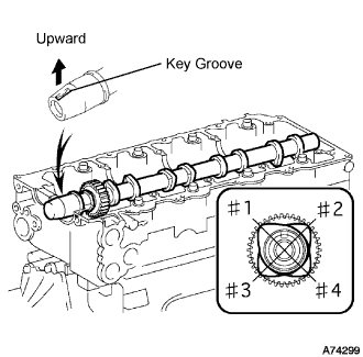 |
Place the camshaft to the cylinder head as shown in the illustration.
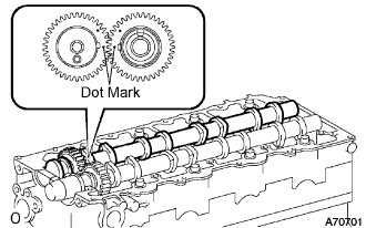 |
Align the dot marks of the camshaft and No.2 camshaft by meshing the both gears before placing the No.2 camshaft.
Remove old packing (FIPG) from the camshaft bearing cap.
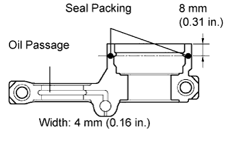 |
Apply seal packing to the specific places shown in the illustration.
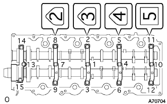 |
Install the camshaft bearing cap as shown in the illustration.
Tighten the 15 bolts for the camshaft bearing cap in the specified order shown in the illustration.
Adjust and inspect valve clearance.
Fix the timing belt cover No.2 with the 4 bolts and nuts.
Tighten the bolt for the camshaft timing pulley while holding the camshaft with a monkey wrench.
Adjust and inspect the valve clearance. (Click here)
Remove the camshaft timing pulley and timing belt cover No.2.
| 2. INSTALL CAMSHAFT SETTING OIL SEAL |
Apply a bit of MP grease to a new oil seal's lip.
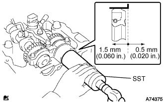 |
Using SST and a hammer, fit the oil seal.
| 3. INSTALL INJECTOR ASSEMBLY |
| 4. CHECK NOZZLE LEAKAGE PIPE LEAK |
| 5. INSTALL TIMING BELT NO.2 COVER |
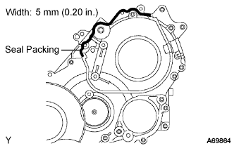 |
Remove old seal packing (FIPG) from the timing gear case.
Apply seal packing to the specific places shown in the illustration.
Fix the timing belt cover No.2 with the 4 bolts and nuts.
| 6. INSTALL TIMING BELT IDLER SUB-ASSEMBLY NO.1 |
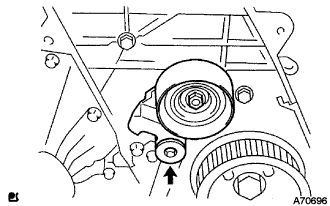 |
Using a 10 mm socket hexagon wrench, install the new plate washer and timing belt idler No.1.
| 7. INSTALL CAMSHAFT TIMING PULLEY |
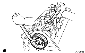 |
Install the camshaft timing pulley.
Tighten the bolt for the camshaft timing pulley while holding the camshaft with a monkey wrench.
| 8. PISTON AND VALVE BREAK PREVENT WORK |
|
When turning the camshaft with the timing belt removed, turn the crankshaft 90° counterclockwise.
| 9. INSTALL TIMING BELT |
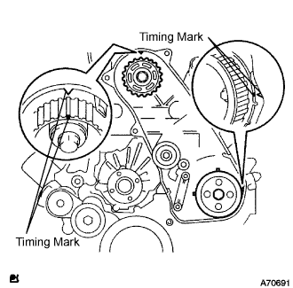 |
Check that the timing marks are aligned as shown in the illustration.
Install the timing belt to pump drive shaft pulley, camshaft timing pulley and timing belt idler No.1 in sequence.
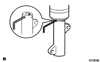 |
Set the tensioner to the press upright.
Using a press, slowly apply 981 to 9,807 N (100 to 1,000 kgf, 220 to 2,205 lbf) of force to the push rod.
Align the holes of push rod and housing, pass a 1.27 mm hexagon wrench through the holes to keep the setting position of the push rod.
Temporarily install the timing belt tensioner with the 2 bolts while pushing the idler pulley toward the timing belt.
Tighten the 2 bolts.
Remove the 1.5 mm hexagon wrench from the tensioner.
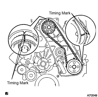 |
Turn the crankshaft in the clockwise direction twice, check that the timing marks are aligned as shown in the illustration.
| 10. INSTALL TIMING BELT NO.1 COVER |
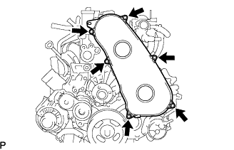 |
Install the timing belt No.1 cover with the 6 bolts.
Install the wire harness clamp.
| 11. INSTALL CYLINDER HEAD COVER SUB-ASSEMBLY |
Remove old seal packing (FIPG) from the cylinder head.
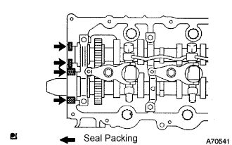 |
Apply a seal packing to the specific places described in the illustration.
Install the cylinder head cover with 10 bolts and 2 nuts.
Connect the ventilation hose.
Install a new nozzle holder seal.
| 12. INSTALL INJECTION PIPE |
Install the injection pipes.
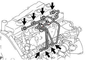 |
Temporarily install the 4 injection pipes.
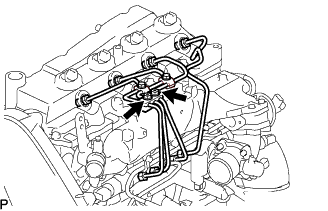 |
Install the injection pipe clamp No.3 in 2 nuts.
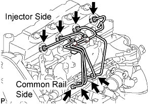 |
Fasten the union sequentially, from the injection pipe common rail to the injector, using SST.
| 13. INSTALL VANE PUMP OIL RESERVOIR ASSEMBLY |
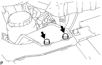 |
Install the vane pump oil reservoir assembly with the 2 bolts.
| 14. INSTALL FAN AND GENERATOR V BELT |
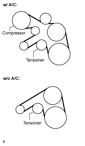 |
Install the drive belt by rotating the tensioner pulley in clockwise direction with the pulley set bolt of the tensioner.
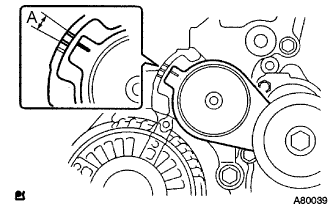 |
Make sure that the indicator mark of the tensioner is within range A.
| 15. INSTALL ENGINE SERVICE HOLE SUB COVER SUB-ASSEMBLY |
Install the engine service hole sub cover with the 5 bolts.
| 16. INSTALL FRONT DOOR SCUFF PLATE RH |
| 17. INSTALL FRONT SEAT ASSEMBLY RH (for Hi-back Seat Type) |
Perform the same procedure as above on the opposite side.
| 18. INSTALL FRONT SEAT ASSEMBLY RH (for Low-back Seat Type) |
Perform the same procedure as above on the opposite side.
| 19. CONNECT BATTERY NEGATIVE TERMINAL |
| 20. ADD ENGINE COOLANT |
Firmly tighten the drain plugs and fill the radiator reserve tank assembly with coolant to the top of the inlet.
Loosen the bleeder plug of outlet housing.
When air is bled and the coolant drains out, firmly install the bleeder plug.
Add coolant up to the B line mark in the radiator reserve tank assembly and install the radiator cap.
| Condition | Capacity |
| w/ rear heater | 17.0 liters (18.0 US qts, 15.0 imp. qts) |
| w/o rear heater | 15.0 liters (15.9 US qts, 13.2 imp. qts) |
Warm up the engine.
After the engine cools down check that the coolant level is between the LOW and FULL level marks.
| 21. BLEED FUEL LINE |
Push the priming pump for several times to fill up the fuel lines with fuel.
| 22. CHECK FUEL LEAK |
PERFORM ACTIVE TEST
Connect the intelligent tester to the DLC3.
Turn the ignition switch on.
Turn the intelligent tester on.
Enter the following menus: Powertrain / ECD / Active Test.
Perform the Active Test.
| Intelligent Tester Display | Test Details | Control Range | Diagnostic Notes |
| Test the Fuel Leak | Pressurizes common rail internal fuel pressure, and checks for fuel leaks | Stop/Start |
|
| 23. CHECK FOR ENGINE OIL LEAKS |
| 24. CHECK FOR ENGINE COOLANT LEAKS |
Fill the radiator with coolant and attach a radiator cap tester to the radiator.
Warm up the engine.
Using a radiator cap tester, increase the pressure inside the radiator to 137 kPa (1.4 kgf/cm2, 19.9 psi), and check that the pressure does not drop.
| 25. INSTALL ENGINE UNDER COVER NO.1 (w/ Engine Under Cover No.1) |
| 26. CHECK IDLE SPEED |
Connect the intelligent tester to the DLC3.
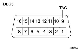 |
If the tester is not available, connect a tester probe of a tachometer to terminal 9 (TAC) of the DLC3 with SST.
Start the engine and check the idle speed.
In case of the tester probe of the tachometer is connected to the DLC3, disconnect the tester probe from terminal 9 of the DLC3 with SST.
Disconnect the intelligent tester from the DLC3.
| 27. INSPECT MAXIMUM ENGINE SPEED |
Connect the intelligent tester to the DLC3.
|
If the tester is not available, connect a tester probe of a tachometer to terminal 9 (TAC) of the DLC3 with SST.
Start the engine.
Depress the accelerator pedal all the way to the limit.
Check the maximum speed.
In case of the tester probe of the tachometer is connected to the DLC3, disconnect the tester probe from terminal 9 of the DLC3 with SST.
Disconnect the intelligent tester from the DLC3.
| 28. PERFORM INITIALIZATION |