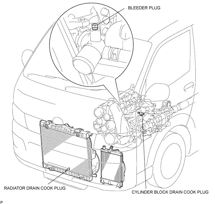
Loosen the radiator drain cock plug and a cylinder block drain cock plug. Then drain the coolant.
CYLINDER HEAD > REMOVAL |
| 1. SEPARATE BATTERY NEGATIVE TERMINAL |
| 2. REMOVE FRONT WHEEL |
| 3. REMOVE ENGINE UNDER COVER NO.1 (w/ Engine Under Cover No.1) |
| 4. DRAIN ENGINE COOLANT |
Remove the radiator cap.
Loosen the radiator drain cock plug and a cylinder block drain cock plug. Then drain the coolant.
| 5. REMOVE FRONT SEAT ASSEMBLY RH (for Hi-back Seat Type) |
Perform the same procedure as above on the opposite side.
| 6. REMOVE FRONT SEAT ASSEMBLY RH (for Low-back Seat Type) |
Perform the same procedure as above on the opposite side.
| 7. REMOVE FRONT DOOR SCUFF PLATE RH |
| 8. REMOVE ENGINE SERVICE HOLE SUB COVER SUB-ASSEMBLY |
Roll up the carpet, and remove the engine service hole sub cover assembly.
| 9. REMOVE FAN AND GENERATOR V BELT |
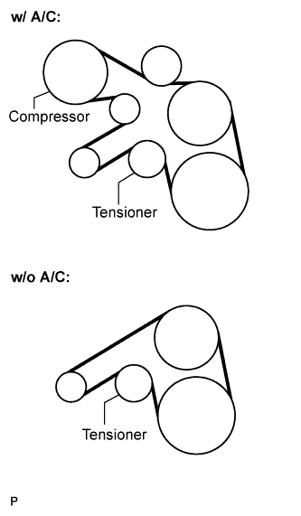 |
Remove the drive belt by rotating the tensioner pulley in clockwise direction to loosen its tension with the pulley set bolt of the tensioner.
| 10. REMOVE EXHAUST PIPE ASSEMBLY FRONT |
Remove the 4 bolts, 2 nuts, 2 compression springs. exhaust pipe assembly front and 2 gaskets.
Disconnect the exhaust pipe support, and remove the exhaust pipe assembly front and 2 gaskets.
| 11. REMOVE FENDER APRON MUDGUARD SEAL RH |
| 12. REMOVE AIR TUBE ASSEMBLY |
Remove the 2 clamps, 2 bolts and air tube assembly.
| 13. REMOVE AIR CLEANER HOSE ASSEMBLY |
Remove the bolt and air cleaner hose assembly.
| 14. REMOVE COMPRESSOR OUTLET ELBOW |
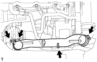 |
Remove the 2 bolts and 2 clamps, then remove the compressor outlet elbow.
| 15. SEPARATE COMPRESSOR AND MAGNETIC CLUTCH (w/ Air Conditioning) |
Disconnect the connector.
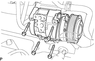 |
Remove the 4 bolts and compressor and magnetic clutch.
| 16. REMOVE COMPRESSOR BRACKET |
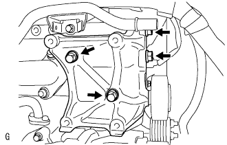 |
Remove the 4 bolts and compressor bracket.
| 17. REMOVE VENTILATION PIPE |
Remove the bolt and ventilation pipe.
| 18. REMOVE VENTILATION HOSE INSULATOR HEAT |
Remove the 2 bolts and ventilation hose insulator heat.
| 19. REMOVE TURBOCHARGER SUB-ASSEMBLY |
| 20. DISCONNECT OIL RETURN HOSE (w/ Intercooler) |
| 21. DISCONNECT AIR HOSE NO.4 |
Remove the clamp, and disconnect the air hose No.4 from the diesel throttle body.
| 22. DISCONNECT RADIATOR HOSE NO.4 |
Remove the clamp, and disconnect the radiator hose No.4 from the water outlet.
| 23. DISCONNECT WATER BY-PASS HOSE NO.3 |
Remove the clamp, and disconnect the water by-pass hose No.3 from the water by-pass pipe.
| 24. SEPARATE VANE PUMP OIL RESERVOIR ASSEMBLY |
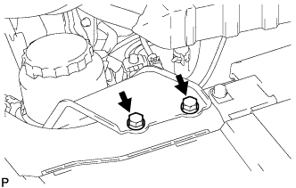 |
Remove the 2 bolts and vane pump oil reservoir assembly.
| 25. REMOVE TIMING BELT NO.1 COVER |
Remove the wire harness clamp.
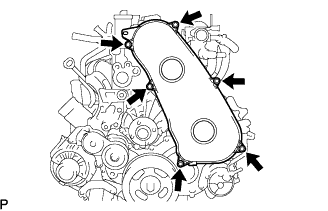 |
Remove the 6 bolts and timing belt cover No.1.
| 26. REMOVE ENGINE SERVICE HOLE COVER NO.2 |
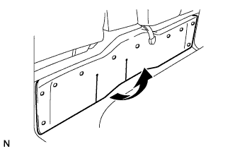 |
Roll up the carpet.
Remove the 3 bolts and the engine service hole cover No.2.
| 27. REMOVE DIESEL THROTTLE BODY ASSEMBLY |
| 28. REMOVE INTAKE AIR CONNECTOR (w/o EGR Valve) |
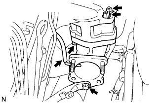 |
Remove the bolt, and separate the manifold stay.
Disconnect the vacuum hose from intake air connector.
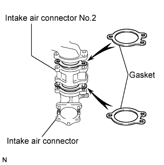 |
Remove the bolt, 2 nuts and the intake air connector assembly.
Remove the 2 gaskets and intake air connector No.2 from the intake air connector.
| 29. REMOVE ELECTRIC EGR CONTROL VALVE ASSEMBLY (w/ EGR Valve) |
Remove the vacuum regulating valve.
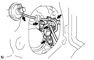 |
Remove the 2 vacuum hoses and the vacuum regulating valve connector.
Remove the 2 bolts and the vacuum regulating valve.
Remove the EGR valve assembly with the sensor.
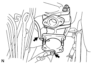 |
Remove the bolt, and separate the manifold stay.
Disconnect the vacuum hose from the intake air connector.
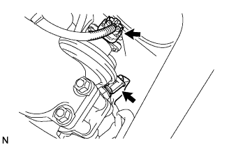 |
Disconnect the intake air temperature sensor connector.
Disconnect the EGR valve position sensor connector.
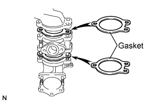 |
Remove the bolt, 2 nuts and the intake air connector assembly.
Remove the 2 gaskets and EGR valve assembly from the intake air connector.
| 30. REMOVE OIL LEVEL GAUGE GUIDE |
Remove the oil level gauge.
Remove the bolt and oil level gauge guide.
| 31. REMOVE INJECTION PIPE |
Remove the injection pipe.
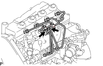 |
Remove the 2 nuts and injection pipe clamp No.3.
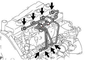 |
Using SST, remove the 4 injection pipes.
| 32. REMOVE FUEL INLET PIPE SUB-ASSEMBLY |
Using SST, remove the fuel inlet pipe sub-assembly.
| 33. REMOVE NOZZLE LEAKAGE PIPE ASSEMBLY NO.2 |
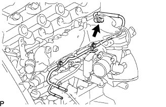 |
Remove the union bolt and gasket.
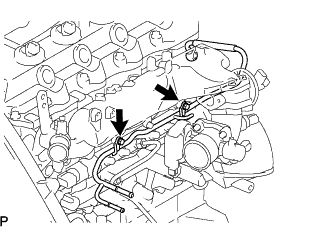 |
Remove the 2 bolts and the nozzle leakage pipe assembly No.2.
| 34. REMOVE CYLINDER HEAD COVER SUB-ASSEMBLY |
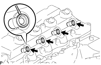 |
Using a small screwdriver, remove the holder seal by prying the portion between the holder seal and the cutout part of the cylinder head.
Disconnect the ventilation hose.
Remove the 10 bolts, 2 nuts, cylinder head cover and gasket.
| 35. SET NO.1 CYLINDER TO TDC/ COMPRESSION |
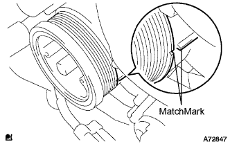 |
Align the matchmarks of the crankshaft pulley and timing gear case cover by rotating the crankshaft in clockwise direction.
| 36. REMOVE TIMING BELT |
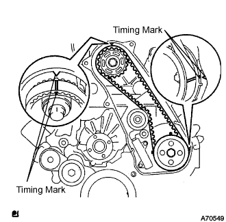 |
Turn the crankshaft in the clockwise direction and align the timing marks as shown in the illustration.
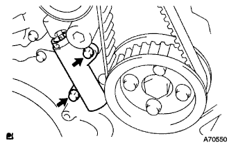 |
Uniformly loosen the 2 bolts, and remove the chain tensioner assembly No.1.
Remove the timing belt.
| 37. REMOVE CAMSHAFT TIMING PULLEY |
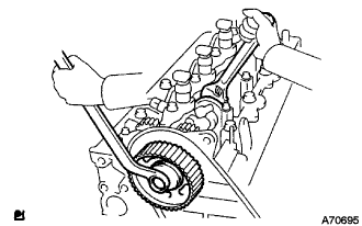 |
Remove the bolt for the camshaft timing pulley while holding the camshaft with a monkey wrench.
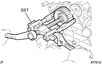 |
Using SST, remove the camshaft timing pulley.
| 38. REMOVE TIMING BELT IDLER SUB-ASSEMBLY NO.1 |
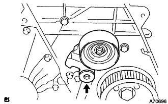 |
Using a 10 mm socket hexagonal wrench remove the timing belt idler No.1.
| 39. REMOVE TIMING BELT NO.2 COVER |
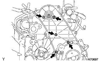 |
Remove the 4 bolts and nuts, then remove the timing belt No.2 cover.
| 40. REMOVE INJECTOR ASSEMBLY |
| 41. REMOVE CAMSHAFT |
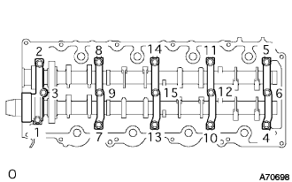 |
Uniformly loosen and remove the 15 camshaft bearing cap bolts in the specified order described in the illustration.
Remove the 5 camshaft bearing caps.
Pull out the oil seal.
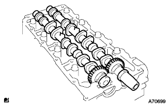 |
Remove the camshaft and No.2 camshaft.
| 42. REMOVE CYLINDER HEAD SUB-ASSEMBLY |
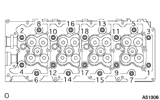 |
Loosen the cylinder head bolts equally and gradually in the order shown in the illustration to remove the bolt and washers.
| 43. REMOVE CYLINDER HEAD GASKET |
| 44. INSPECT CYLINDER HEAD SET BOLT |
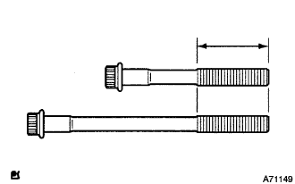 |
Using vernier calipers, measure the outer diameter within the specified area shown in the illustration.