 |
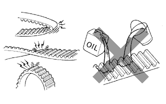
If there is premature parting:
- Check for proper installation.
- Check the timing cover gasket for damage and proper installation.
TIMING BELT > INSTALLATION |
| 1. INSPECT TIMING BELT |
|
If there is premature parting:
If the belt teeth are cracked or damaged, check if either camshaft is locked.
If there is noticeable wear or cracks on the belt face, check if there are nicks on the side of the idler pulley lock and water pump.
If there is wear or damage to only one side of the belt, check the belt guide and the alignment of each pulley.
If there is noticeable wear on the belt teeth:
| 2. INSPECT TIMING BELT IDLER SUB-ASSY NO.1 |
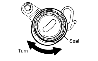 |
Visually check the seal portion of the timing belt idler No.1 for oil leakage.
If leakage is found, replace the timing belt idler No.1.
Check that the timing belt idler No.1 turns smoothly.
If necessary, replace the timing belt idler No.1.
| 3. INSPECT IDLER TENSION SPRING |
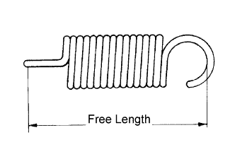 |
Measure the free length of the tension spring.
Measure the tension of the tension spring at the specified installed length.
| 4. INSPECT WATER PUMP ASSY |
| 5. SET NO.1 CYLINDER TO TDC/ COMPRESSION |
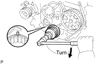 |
Using the crankshaft pulley bolt, align its groove with the timing pointer by turning the crankshaft clockwise.
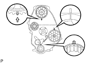 |
Set the timing and drive pulleys at each position.
| 6. INSTALL TIMING BELT |
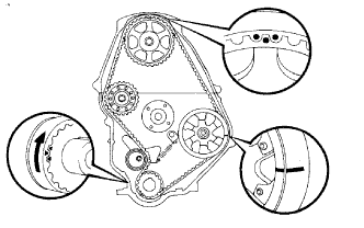 |
Remove any oil or water on each pulleys, and keep them clean.
Install the timing belt on the crankshaft timing and timing belt idlers.
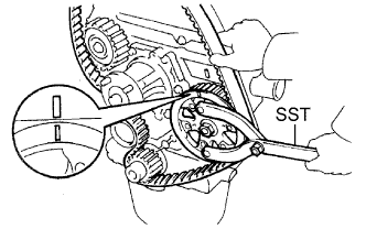 |
Using SST, slightly turn the injection pump drive pulley clockwise. Hang the timing belt on the pulley, and align the timing marks of the drive pulley and timing belt case.
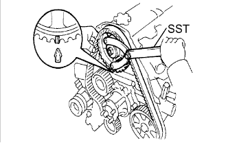 |
Using SST, slightly turn the camshaft timing pulley clockwise. Hang the timing belt on the timing pulley, and align the timing marks of the timing pulley and timing belt case.
Check that the timing belt has tension between the injection pump drive and camshaft timing pulleys.
Install the timing belt on the timing belt idler No.2.
| 7. CHECK VALVE TIMING |
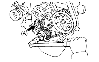 |
Loosen the timing belt idler No.1 bolt (A), and stretch the timing belt.
Slowly turn the crankshaft pulley 2 revolutions from TDC to TDC.
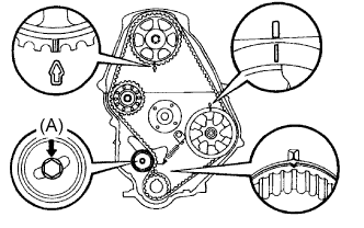 |
Check each pulley aligns with the timing marks as shown in the illustration.
If the timing marks do not align, remove the timing belt and reinstall it.
Tighten the timing belt idler No.1 bolt (A).
| 8. INSTALL TIMING BELT GUIDE |
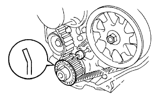 |
Install the belt guide with the cup side facing outward.
| 9. INSTALL TIMING CHAIN OR BELT COVER SUB-ASSEMBLY |
Remove the 2 nuts and wire harness clamp bracket.
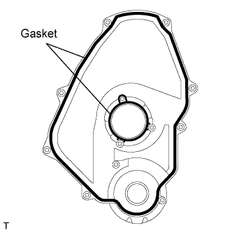 |
Install the 2 gaskets to the timing belt cover.
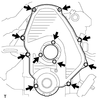 |
Install the timing belt cover with the 11 bolts.
Install the 2 nuts and wire harness clamp bracket.
| 10. INSTALL CRANKSHAFT PULLEY |
Align the pulley set key with the key groove of the pulley, and slide the pulley to the crankshaft.
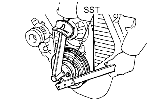 |
Using SST, install the pulley bolt.
| 11. INSTALL VANE PUMP DRIVE PULLEY |
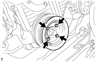 |
w/o Air conditioning:
Install the vane pump drive pulley and vane pump pulley spacer with the 4 bolts.
w/ Air conditioning:
Install the 2 vane pump drive pulleys with the 4 bolts.
| 12. INSTALL COMPRESSOR MOUNTING BRACKET (w/ Air Conditioning) |
Temporarily install the compressor mounting bracket with the 4 bolts.
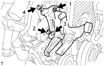 |
Using several steps, uniformly install and tighten the 4 bolts in the sequence shown in the illustration.
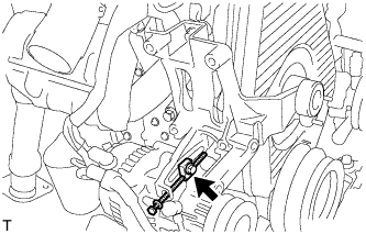 |
Temporarily tighten the bolt and spacer.
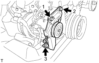 |
Temporarily install the compressor mounting bracket with the 3 bolts.
Using several steps, uniformly install and tighten the 3 bolts in the sequence shown in the illustration.
| 13. INSTALL COMPRESSOR AND MAGNETIC CLUTCH (w/ Air Conditioning) |
| 14. TEMPORARILY TIGHTEN FAN PULLEY |
Temporarily tighten the fan pulley with the 4 bolts.
| 15. INSTALL FAN AND GENERATOR V BELT (w/o Air Conditioning) |
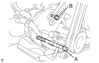 |
Install the V belt.
Using a bar, adjust the tension of the V belt.
Tighten the bolts A and B.
Check the tension of the V belt. (Click here)
| 16. INSTALL FAN AND GENERATOR V BELT (w/ Air Conditioning) |
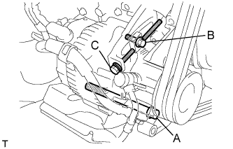 |
Install the V belt.
Tightening the bolt C, adjust the tension of the V belt.
Tighten the bolts A and B.
Check the tension of the V belt. (Click here)
| 17. TIGHTEN FAN PULLEY |
Install the 4 nuts, fan spacer and fan pulley.
| 18. INSTALL V (COOLER COMPRESSOR TO CRANKSHAFT PULLEY) BELT NO.1 (w/ Air Conditioning) |
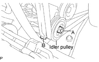 |
Install the V belt.
Tightening the bolt B, adjust the tension of the V belt.
Tighten nut A.
Check the tension of the V belt. (Click here)
| 19. INSTALL VANE PUMP V BELT |
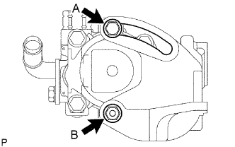 |
Install the V belt.
Using a bar, adjust the tension of the V-ribbed belt.
Tighten the bolt A and nut B.
Check the tension of the V belt. (Click here)
| 20. INSTALL ENGINE SERVICE HOLE SUB COVER SUB-ASSEMBLY |
Install the 5 bolts and engine service hole cover.
| 21. INSTALL FRONT DOOR SCUFF PLATE RH |
| 22. INSTALL FRONT SEAT ASSEMBLY RH (for Hi-back Seat Type) |
| 23. INSTALL FRONT SEAT ASSEMBLY RH (for Low-back Seat Type) |
| 24. CONNECT CABLE TO NEGATIVE BATTERY TERMINAL |
| 25. ADD ENGINE COOLANT |
Close the engine drain plug.
Close the radiator drain cock plug.
Slowly fill the cooling system with coolant.
Slowly pour coolant into the radiator reserve tank until it reaches the FULL line.
Install the radiator cap to the radiator reserve tank.
Press the inlet and outlet radiator hoses several times by hand while warming up the engine.
Stop the engine, and wait until the engine coolant cools down.
Add coolant to the FULL line of the radiator reservoir.
| 26. CHECK FOR ENGINE COOLANT LEAKS |
Fill the radiator with coolant and attach a radiator cap tester to the radiator.
Warm up the engine.
Using a radiator cap tester, increase the pressure inside the radiator to 118 kPa (1.2 kgf/cm2, 17.1 psi), and check that the pressure does not drop.
| 27. CHECK IDLE SPEED |
Warm up the engine.
When using an intelligent tester:
Connect the intelligent tester to the DLC3.
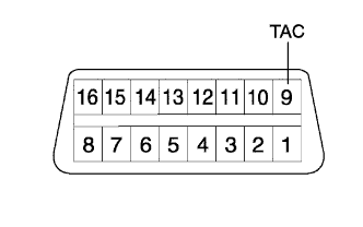 |
When not using an intelligent tester:
Using SST, connect the tachometer test probe to terminal 9 (TAC) of the DLC3.
Check the idle speed.
| 28. INSPECT MAXIMUM ENGINE SPEED |
Start the engine.
Depress the accelerator pedal all the way.
Check the maximum speed.
| 29. PERFORM INITIALIZATION |