INSTALLATION
Removal / installation · Vehicles built from Dec 2017
Versions by build date: Oct 2014 – Dec 2014 Jan 2015 – Nov 2015 Dec 2015 – Mar 2016 Apr 2016 – Dec 2016 Jan 2017 – Nov 2017 from Dec 2017
| 1.
INSTALL FRONT AXLE HUB BEARING |
 |
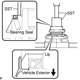
- Using SST and a press, install a new front axle hub bearing.
- SST
- 09649-17010
09950-70010
(09951-07100)
- NOTICE:
- Do not press on or damage the bearing seal of the front axle hub bearing.
- HINT:
- Make sure the lip of the front axle hub bearing faces the vehicle exterior.
| 2.
INSTALL FRONT DISC |
|
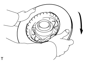
- Install the front disc as shown in the illustration.
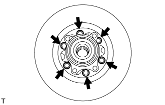
- Install the front disc with the 6 bolts.
-
Torque:
- 62 N*m{
632 kgf*cm
, 46 ft.*lbf
}
| 3.
INSTALL FRONT WHEEL ADJUSTING NUT (w/ ABS) |
|
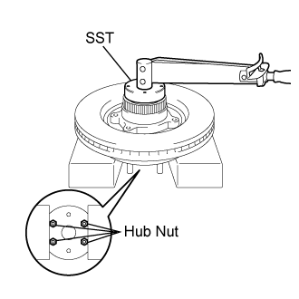
Install the hub nut to the front axle hub bolt.
Hold the front axle assembly in a vise between aluminium plates.
- NOTICE:
- Do not overtighten the vise.
- Hold the hub nut in a vise to secure the axle hub and bearing assembly.
- Install the skid control rotor as shown in the illustration.
- Using SST, install the front wheel adjusting nut.
- SST
- 09607-26010
-
Torque:
- 287 N*m{
2,930 kgf*cm
, 212 ft.*lbf
}
- NOTICE:
- Do not use an extension bar to avoid applying excess torque to the nut and rotor.
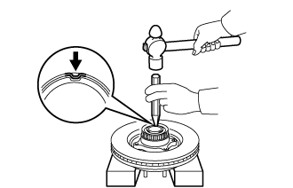
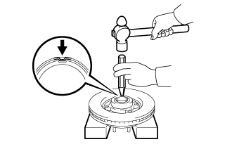
- Using a chisel and hammer, stake the front wheel adjusting nut.
| 4.
INSTALL FRONT WHEEL ADJUSTING NUT (w/o ABS) |
|
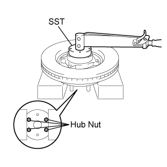
Install the hub nut to the front axle hub bolt.
Hold the front axle assembly in a vise between aluminium plates.
- NOTICE:
- Do not overtighten the vise.
- Hold the hub nut in a vise to secure the axle hub and bearing assembly.
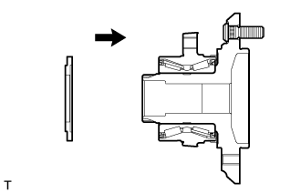
- Install the front wheel bearing dust deflector as shown in the illustration.
- Using SST, install the front wheel adjusting nut.
- SST
- 09607-26010
-
Torque:
- 287 N*m{
2,930 kgf*cm
, 212 ft.*lbf
}
- NOTICE:
- Do not use an extension bar to avoid applying excess torque to the nut and rotor.
- Using a chisel and hammer, stake the front wheel adjusting nut.
| 5.
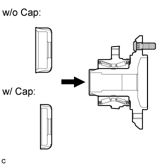
INSTALL INNER KNUCKLE GREASE RETAINER CAP (w/ Cap) |
|
| 6.
INSTALL FRONT LOWER BALL JOINT ASSEMBLY |
|
| 7.
INSTALL STEERING KNUCKLE |
|
| 8.
INSTALL OUTER KNUCKLE GREASE RETAINER CAP (w/ Cap) |
|
| 9.
INSTALL FRONT AXLE ASSEMBLY |
|
| 10.
INSTALL TIE ROD END SUB-ASSEMBLY |
|
| 11.
INSTALL FRONT DISC BRAKE CALIPER ASSEMBLY |
|
| 12.
INSTALL FRONT SPEED SENSOR (w/ ABS) |
|
| 13.
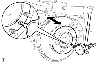
INSPECT FRONT AXLE HUB BEARING LOOSENESS |
|
- Using a dial indicator, check for runout on the surface of the front axle hub outside the hub bolt.
- Maximum:
- 0.07 mm (0.0028 in.)
- NOTICE:
- Ensure that the dial indicator is set at right angles to the measurement surface.
If runout exceeds the maximum, replace the front axle hub.
| 14.
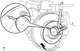
INSPECT FRONT AXLE HUB RUNOUT |
|
- Using a dial indicator, check for looseness near the center of the front axle hub.
- Maximum:
- 0.05 mm (0.0020 in.)
- NOTICE:
- Ensure that the dial indicator is set at right angles to the measurement surface.
If looseness exceeds the maximum, replace the bearing.
| 15.
INSTALL FRONT WHEEL |
|
-
Torque:
- 100 N*m{
1,020 kgf*cm
, 74 ft.*lbf
}
| 16.
INSPECT WHEEL ALIGNMENT |
|
(Click here)
| 17.
CHECK ABS SPEED SENSOR SIGNAL |
|
- w/ VSC: (Click here)
- w/o VSC: (Click here)