REMOVAL
Removal / installation · Vehicles built from Oct 2014
| 1. REMOVE FRONT WHEEL |
| 2. SEPARATE FRONT SPEED SENSOR (w/ ABS) |

Remove the 2 bolts, and separate the speed sensor from the steering knuckle.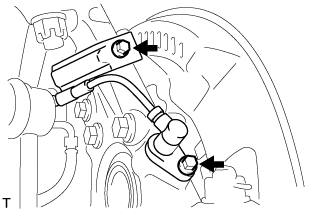

- NOTICE:
- Be careful not to damage the speed sensor.
- Prevent foreign matter from adhering to the speed sensor.
- Be careful not to damage the speed sensor.
| 3. SEPARATE FRONT DISC BRAKE CALIPER ASSEMBLY |
Remove the 2 bolts, and disconnect the brake caliper assembly.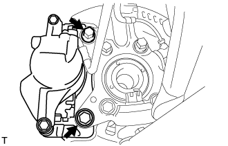
- NOTICE:
- Use a wire or an equivalent to keep the brake caliper from hanging down by the flexible hose.
| 4. SEPARATE TIE ROD END SUB-ASSEMBLY |
Remove the cotter pin and castle nut.
Using SST, separate the tie rod end from the steering knuckle.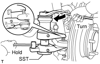
- SST
- 09628-00011
- NOTICE:
- Do not damage the ball joint dust boot.
- Do not damage the brake dust cover.
- Make sure that the string of the SST is securely tied to the vehicle.
- Do not damage the ball joint dust boot.
| 5. REMOVE FRONT AXLE ASSEMBLY |
Remove the 4 bolts, 4 nuts and front axle assembly from the front suspension lower arm.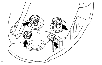
Remove the cotter pin and castle nut.
Using SST, remove the front axle assembly from the front suspension upper arm.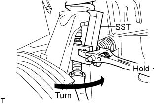
- SST
- 09628-62011
- NOTICE:
- Do not damage the ball joint dust boot.
- Apply grease to the threads and tip of the SST center bolt before use.
- Make sure that the string of the SST is securely tied to the vehicle.
- Do not damage the ball joint dust boot.
| 6. REMOVE FRONT LOWER BALL JOINT ASSEMBLY |
Fix the steering knuckle in the vise using aluminium plates.
- NOTICE:
- Do not damage the steering knuckle.
Remove the cotter pin.
Loosen the nut.
Using SST, separate the front lower ball joint assembly from the steering knuckle.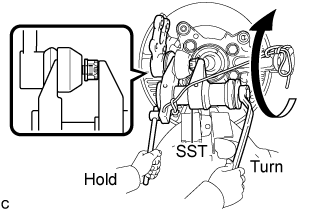
- SST
- 09628-00011
- NOTICE:
- Do not damage the ball joint dust boot.
- Make sure that the string of the SST is securely tied to the steering knuckle.
- Do not damage the ball joint dust boot.
Remove the nut and front lower ball joint assembly.
| 7. REMOVE INNER KNUCKLE GREASE RETAINER CAP (w/ Cap) |
Using a chisel, make a hole in the center of the outer knuckle grease retainer cap to insert a brass bar.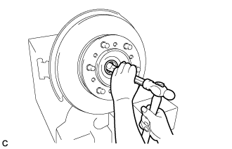
Using a brass bar, remove the inner knuckle grease retainer cap from the steering knuckle as shown in the illustration.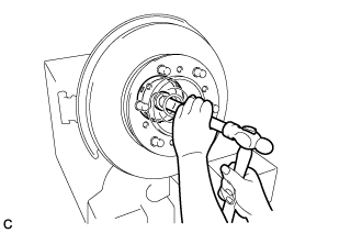
| 8. REMOVE OUTER KNUCKLE GREASE RETAINER CAP (w/ Cap) |
Using SST, remove the outer knuckle grease retainer cap.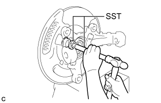
- SST
- 09950-60010
(09951-00300)
09950-70010 (09951-07200)
| 9. REMOVE STEERING KNUCKLE |
Remove the 4 bolts.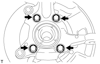
Using SST, remove the steering knuckle, brake dust cover from the front axle hub sub-assembly.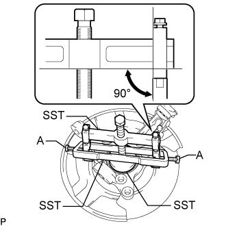
- SST
- 09950-40011
(09951-04020, 09952-04010, 09953-04010, 09958-04011)
09950-60010 (09951-00470)
09955-04140
09958-04030
- NOTICE:
- Apply grease to the threads and tip of the SST center bolt (09953-04010) before use.
- Make sure that the slide arm (09952-04010) is at a 90° angle to the hanger 200 (09951-04020) when using SST.
- Make sure that the claw No. 14 (09955-04140) is securely attached to the steering knuckle.
- Apply grease to the threads and tip of the SST center bolt (09953-04010) before use.
- HINT:
- For bolt A, use the bolt for the holder (09958-04011).
| 10. REMOVE FRONT WHEEL ADJUSTING NUT (w/ ABS) |
Install the hub nut to the front axle hub bolt.
Hold the axle hub and bearing assembly in a vise between aluminium plates.
- NOTICE:
- Do not overtighten the vise.
- Hold the hub nut in a vise to secure the axle hub and bearing assembly.
- Do not overtighten the vise.
Using SST and a hammer, release the staked part of the front wheel adjusting nut.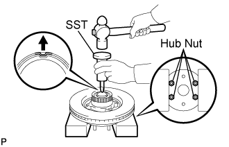
- SST
- 09930-00010
- NOTICE:
- Release the staked part of the nut completely, otherwise the threads of the front axle hub may be damaged.
Using SST, remove the front wheel adjusting nut and skid control rotor.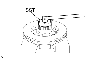
- SST
- 09607-26010
- NOTICE:
- Do not use an extension bar to avoid applying excess torque to the nut and rotor.
| 11. REMOVE FRONT WHEEL ADJUSTING NUT (w/o ABS) |
Install the hub nut to the front axle hub bolt.
Hold the axle hub and bearing assembly in a vise between aluminium plates.
- NOTICE:
- Do not overtighten the vise.
- Hold the hub nut in a vise to secure the axle hub and bearing assembly.
- Do not overtighten the vise.
Using SST and a hammer, release the staked part of the front wheel adjusting nut.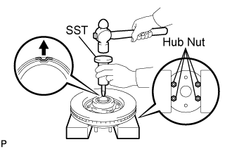
- SST
- 09930-00010
- NOTICE:
- Release the staked part of the nut completely, otherwise the threads of the front axle hub may be damaged.
Using SST, remove the front wheel adjusting nut and front wheel bearing dust deflector No.1.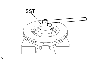
- SST
- 09607-26010
- NOTICE:
- Do not use an extension bar to avoid applying excess torque to the nut and rotor.
| 12. REMOVE FRONT DISC |
Remove the 6 bolts.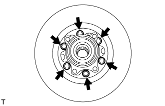
Remove the front disc as shown in the illustration.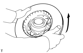
| 13. REMOVE FRONT AXLE HUB BEARING |
Using SST, remove the front axle hub bearing from the front axle hub sub-assembly.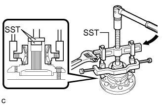
- SST
- 09950-40011
(09951-04020, 09952-04010, 09953-04020, 09954-04010, 09955-04031, 09957-04010, 09958-04011)
09950-60010 (09951-00360, 09951-00480, 09952-06010)
- NOTICE:
- Apply a small amount of grease to the threads and tip of SST (center bolt) before use.
Using SST, remove the front axle hub bearing (inner race) from the front axle hub sub-assembly.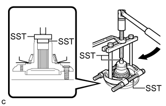
- SST
- 09950-00020
09950-00030
09950-40011 (09957-04010)
09950-60010 (09951-00360, 09951-00480, 09952-06010)
- NOTICE:
- Apply a small amount of grease to the threads and tip of SST (center bolt) before use.