2014-2019 Hiace · Service Manual ENGINE

REMOVAL

Removal / installation · Vehicles built Oct 2014 – Dec 2016

Versions by build date: Oct 2014 – Dec 2016 from Jan 2017


1. PLACE FRONT WHEELS FACING STRAIGHT AHEAD

2. WORK FOR PREVENTING GASOLINE FROM SPILLING OUT
(Click here)

3. SEPARATE BATTERY NEGATIVE CABLE

4. REMOVE FRONT WHEELS

5. REMOVE ENGINE UNDER COVER NO.1 (w/ Engine Under Cover No.1)

6. REMOVE ENGINE UNDER COVER NO.2 (w/ Engine Under Cover No.2)

7. REMOVE ENGINE SIDE UNDER COVER LH (w/ Engine Side Under Cover LH)

8. REMOVE ENGINE SIDE UNDER COVER RH (w/ Engine Side Under Cover RH)

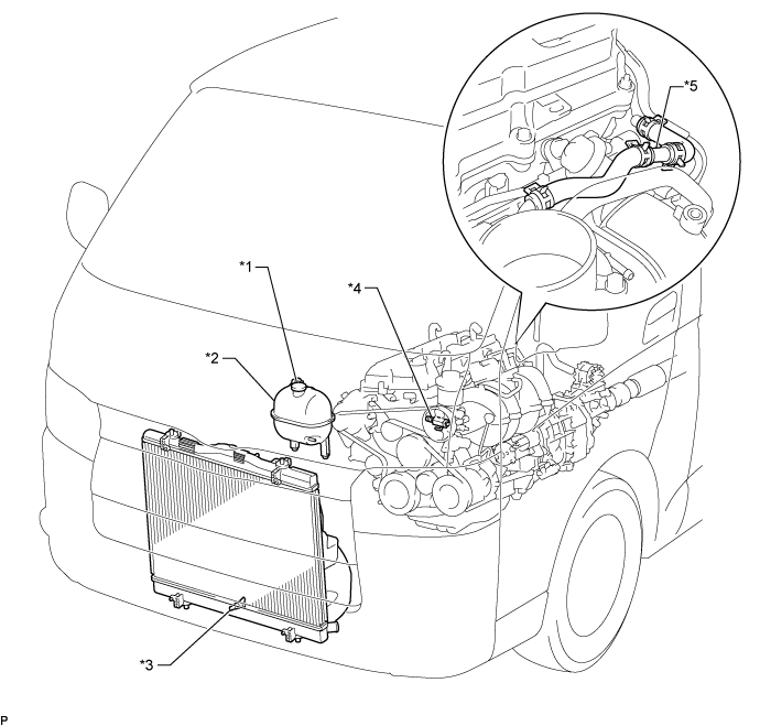
9. DRAIN ENGINE COOLANT

CAUTION:
Do not remove the radiator reservoir cap sub-assembly while the engine and radiator are still hot. Pressurized, hot engine coolant and steam may be released and cause serious burns.

HINT:
Collect the engine coolant in a container and dispose of it according to local regulations.

  1. Loosen the radiator drain cock plug and drain the engine coolant.

    A316495E01

    Text in Illustration 
    *1
    Radiator Reservoir Cap Sub-assembly
    *2
    Radiator Reservoir Assembly
    *3
    Radiator Drain Cock Plug
    *4
    Cylinder Block Water Drain Cock Plug
    *5
    2-Way
    -
    -

  1. Remove the radiator reservoir cap sub-assembly.

  1. Loosen the cylinder block water drain cock plug and drain the engine coolant from the engine.


10. DRAIN ENGINE OIL
  1. Remove the oil filler cap.

  1. Remove the oil drain plug and drain the engine oil from the oil pan.

    NOTICE:
    Collect the oil in a disposable oil container.

  1. Clean the oil pan drain plug and install it with a new gasket.

    Torque:
    45 N*m{ 459 kgf*cm , 33 ft.*lbf }


11. REMOVE FRONT SEAT ASSEMBLY RH (for Hi-back Seat Type)

HINT:
Use the same procedures described for the LH side. (Click here)


12. REMOVE FRONT SEAT ASSEMBLY RH (for Low-back Seat Type)

HINT:
Use the same procedures described for the LH side. (Click here)


13. REMOVE FRONT DOOR SCUFF PLATE

14. REMOVE ENGINE SERVICE HOLE SUB COVER SUB-ASSEMBLY
  1. Roll up the carpet, and remove the 5 bolts and engine service hole sub cover.


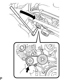
15. REMOVE FAN & GENERATOR V BELT

  1. A102135E01
    Use the hexagon-shaped part indicated by the arrow in the illustration to move the tensioner pulley downward and decrease the tension in the drive belt. Then remove the drive belt.

    NOTICE:
    When removing the drive belt, do not use the idle pulley's bolt.

    HINT:
    After removing the drive belt, move the tensioner upward to the maximum amount.


16. DISCONNECT RADIATOR HOSE INLET
  1. Remove the clamp, and disconnect the radiator hose inlet from the engine.


17. DISCONNECT RADIATOR HOSE OUTLET
  1. Remove the clamp, and disconnect the radiator hose outlet from the engine.


18. DISCONNECT HEATER WATER HOSE INLET A
  1. Disconnect the heater water inlet hose A from the heater unit.


19. DISCONNECT HEATER WATER HOSE OUTLET B
  1. Disconnect the heater water outlet hose B from the heater unit.


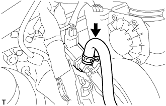
20. DISCONNECT FUEL VAPOR FEED HOSE ASSEMBLY

  1. A103325
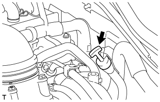
    Disconnect the fuel vapor feed hose from the VSV.


21. DISCONNECT UNION TO CONNECTOR TUBE HOSE
  1. Disconnect the union to connector tube hose from the intake manifold.


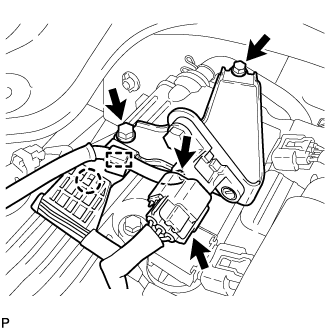
22. REMOVE AIR PRESSURE SENSOR (w/ Manifold Absolute Pressure Sensor)

  1. A259661
    Disconnect the connector.

  1. Disconnect the vacuum hose and clamp.

  1. Detach the wire harness clamp

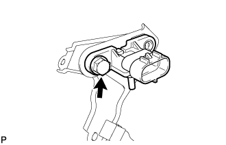
  1. Remove the 2 bolts and air pressure sensor together with the bracket.

  1. A259662
    Remove the bolt and air pressure sensor.


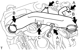
23. REMOVE INTAKE AIR CONNECTOR

  1. A102437E01
    Slide the clamp and disconnect the No. 2 ventilation hose and vacuum hose. (A)

  1. Loosen the 2 hose clamp bolts. (B)

  1. Remove the 2 bolts and intake air connector. (C)


24. DISCONNECT AIR HOSE NO.5 (w/ Secondary Air Injection System)
  1. Disconnect the air hose No.5 from the air switching valve.


25. DISCONNECT FUEL HOSE

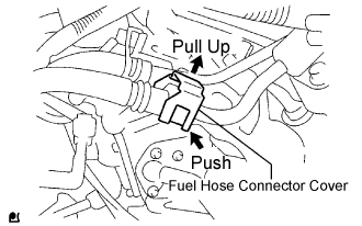
  1. A087751E01
    Pull the fuel hose connector cover up to release the lock. (Click here)

  1. Disengage the fuel connector to disconnect the fuel hose. (Click here)


26. DISCONNECT FUEL HOSE NO.2
  1. Remove the clamp, and disconnect the fuel hose No.2 from the delivery pipe.


27. DISCONNECT VANE PUMP ASSEMBLY

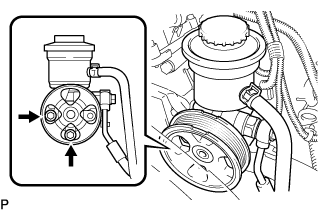
  1. A102130E01
    Disconnect the PS fluid pressure switch connector.

  1. Remove the 2 bolts and disconnect the pump from the engine.

  1. Support the vane pump securely.


28. REMOVE OIL LEVEL GAUGE SUB-ASSEMBLY

29. REMOVE OIL LEVEL GAUGE GUIDE

  1. A102132E01
    Remove the bolt and gauge guide.


30. SEPARATE COMPRESSOR AND MAGNETIC CLUTCH (w/ Air Conditioning System)
  1. Disconnect the compressor connector.

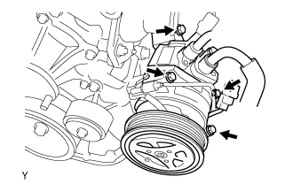
  1. A102804E02
    Remove the 4 bolts and disconnect the compressor from the engine.

    HINT:
    Disconnect the compressor with the low pressure hose and high pressure hose stuck by suspended from the rope.

  1. Support the cooler compressor securely.


31. DISCONNECT ENGINE WIRE
  1. Disconnect the wire harness support of the ECM.

  1. Disconnect the connectors of the ECM.

  1. Disconnect the clamps of the engine wire and earth cable.

  1. Disconnect the +B terminal of the starter and connector from the generator.

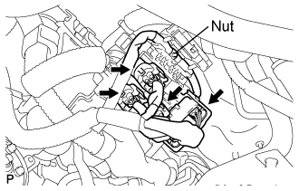
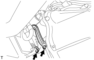
  1. A101143E03
    Remove the nut and disconnect the cable from the engine room J/B.


32. REMOVE EXHAUST PIPE ASSEMBLY FRONT (for Super Long Wheelbase)
  1. w/ Secondary air injection system:

    1. Disconnect the fuel ratio sensor connector.

    2. Remove the fuel ratio sensor. (Click here)

  1. For unleaded gasoline engine:

    1. Disconnect the oxygen sensor connector.

    2. Remove the oxygen sensor. (Click here)

  1. Remove the 4 bolts, 2 nuts, and 2 compression springs.

  1. Remove the 2 gaskets from the exhaust pipe assembly front.

  1. Disconnect the exhaust pipe support, and remove the exhaust pipe assembly front.


33. REMOVE EXHAUST PIPE ASSEMBLY FRONT (for Long Wheelbase)
  1. w/ Secondary air injection system:

    1. Disconnect the fuel ratio sensor connector.

    2. Remove the fuel ratio sensor. (Click here)

  1. For unleaded gasoline engine:

    1. Disconnect the oxygen sensor connector.

    2. Remove the oxygen sensor. (Click here)

  1. Remove the 4 bolts, 2 nuts, and 2 compression springs.

  1. Remove the 2 gaskets from the exhaust pipe assembly front.

  1. Disconnect the exhaust pipe support, and remove the exhaust pipe assembly front.


34. REMOVE EXHAUST PIPE ASSEMBLY CENTER (for Super Long Wheelbase)
  1. Remove the 2 bolts and gasket from the exhaust pipe assembly center.

  1. Disconnect the exhaust pipe supports, and remove the exhaust pipe assembly center.


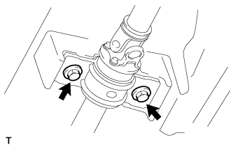
35. REMOVE PROPELLER WITH CENTER BEARING SHAFT ASSEMBLY (for Super Long Wheelbase)

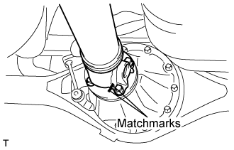
  1. C102185E01
    Put matchmarks on both flanges.

  1. Remove the 4 nuts, bolts and washers.

    HINT:
    If the flange connection is hard to separate, temporarily tighten one nut only and evenly tap the flange with a brass bar and hammer to separate the propeller with center bearing shaft assembly from the differential companion flange.

  1. C107214
    Remove the 2 bolts and center support bearing assembly No.1.

  1. Remove the propeller with center bearing shaft assembly.

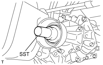
  1. C102186E01
    Insert SST in the transmission to prevent oil leakage.

    NOTICE:
    Do not damage the oil seal.


    1. Use the following SST for the automatic transmission.

      SST
      09325-40010  

    2. Use the following SST for the manual transmission.

      SST
      09325-20010  


36. REMOVE PROPELLER SHAFT ASSEMBLY (for Long Wheelbase)

  1. C102185E01
    Put matchmarks on both flanges.

  1. Remove the 4 nuts, bolts and washers.

    HINT:
    If the flange connection is hard to separate, temporarily tighten one nut only and evenly tap the flange with a brass bar and hammer to separate the propeller shaft assembly from the differential companion flange.

  1. Remove the propeller shaft assembly.

  1. C102186E01
    Insert SST in the transmission to prevent oil leakage.

    NOTICE:
    Do not damage the oil seal.


    1. Use the following SST for the automatic transmission

      SST
      09325-40010  

    2. Use the following SST for the manual transmission

      SST
      09325-20010  


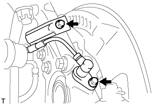
37. REMOVE SPEED SENSOR FRONT LH (w/ ABS)

  1. C102281E01
    Remove the 2 bolts, and separate the speed sensor from the steering knuckle.

    NOTICE:
    1. Be careful not to damage the speed sensor.
    2. Prevent foreign matter from adhering to the speed sensor.


38. REMOVE SPEED SENSOR FRONT RH (w/ ABS)

HINT:
Use the same procedures described for the LH side.


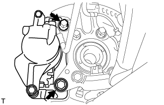
39. REMOVE FRONT DISC BRAKE CALIPER ASSEMBLY LH

  1. C102283E01
    Remove the 2 bolts, and disconnect the brake caliper assembly.

    NOTICE:
    Use a wire or an equivalent to keep the brake caliper from hanging down by the flexible hose.


40. REMOVE FRONT DISC BRAKE CALIPER ASSEMBLY RH

HINT:
Use the same procedures described for the LH side.


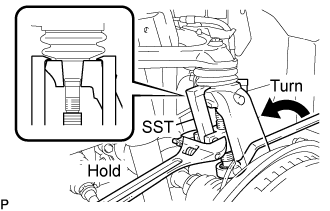
41. SEPARATE FRONT SUSPENSION SUB-ASSEMBLY UPPER LH

  1. C101998E01
    Remove the cotter pin and loosen the nut.
    SST
    09628-62011  

    NOTICE:
    Do not remove the nut.

  1. Using SST, separate the steering knuckle from the suspension upper arm and remove the nut.

    NOTICE:
    1. Fix the steering knuckle with a wire so that the flexible hose does not receive excessive force.
    2. Do not damage the ball joint dust cover.


42. SEPARATE FRONT SUSPENSION SUB-ASSEMBLY UPPER RH

HINT:
Use the same procedures described for the LH side.


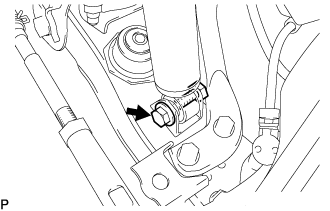
43. SEPARATE SHOCK ABSORBER ASSEMBLY FRONT LH

  1. C102009E02
    Remove the bolt and separate the front shock absorber from the front suspension lower arm.


44. SEPARATE SHOCK ABSORBER ASSEMBLY FRONT RH

HINT:
Use the same procedures described for the LH side.


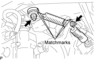
45. SEPARATE TRANSMISSION CONTROL CABLE ASSEMBLY (for Manual Transmission)

  1. C102206E01
    Put matchmarks on the control cable assembly and the outer lever.

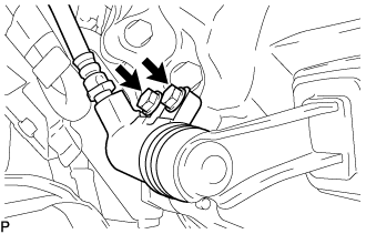
  1. Remove the 2 nuts and separate the transmission control cable from the outer lever.

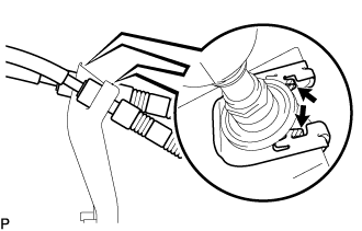
  1. C102207
    Using a screwdriver, disengage the claws of the 2 clips.

  1. Remove the transmission control cable and 2 clips from the transmission control cable bracket No.1.


46. SEPARATE CLUTCH RELEASE CYLINDER ASSEMBLY (for Manual Transmission)

  1. C102209
    Remove the 2 bolts and separate the clutch release cylinder.


47. REMOVE TRANSMISSION OIL LEVEL GAUGE SUB-ASSEMBLY (for Automatic Transmission)

  1. C102919
    Remove the transmission oil level gage sub assembly from the transmission oil filler tube.


48. REMOVE TRANSMISSION OIL FILLER TUBE SUB-ASSEMBLY (for Automatic Transmission)

  1. C102934E01
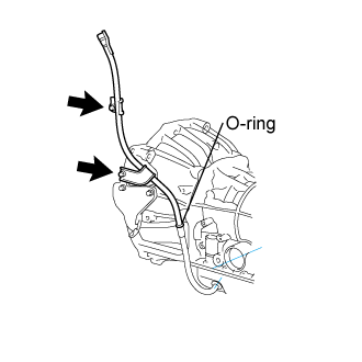
    Remove the 2 bolts transmission oil filler tube sub-assembly.

  1. Remove the O-ring from the oil filler tube sub-assembly.


49. DISCONNECT TRANSMISSION CONTROL CABLE ASSEMBLY (for Automatic Transmission)

  1. C102933E05
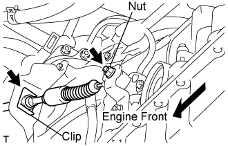
    Remove the nut and disconnect the transmission control cable assembly from the transmission control shaft lever assembly.

  1. Remove the clip and disconnect the transmission control cable assembly from the transmission control cable bracket.


50. DISCONNECT OIL COOLER HOSE (for Automatic Transmission)
  1. Remove each clamp and disconnect the oil cooler inlet hose and oil cooler outlet hose from the oil cooler tube.


51. SEPARATE STEERING TORQUE SHAFT ASSEMBLY

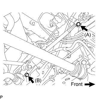
  1. C106142E01
    Loosen bolt (A) and remove bolt (B), then slide the steering torque shaft assembly.

    HINT:
    1. Do not remove bolt (A).
    2. Do not disconnect the steering torque shaft assembly from the power steering link assembly.

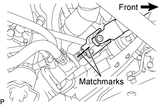
  1. C106143E01
    Put matchmarks on the steering torque shaft assembly and the power steering link assembly.

  1. Separate the steering torque shaft assembly from the power steering link assembly.


52. REMOVE ENGINE ASSEMBLY WITH TRANSMISSION
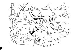
  1. Using the engine lifter, hold the engine assembly and separate the rear engine mount.

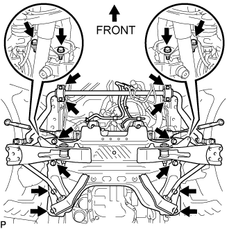
  1. A101144E04
    Remove the stabilizer brackets and 16 bolts of the front suspension cross member.
  1. Remove the engine assembly w/ transmission out of the vehicle slowly and carefully.


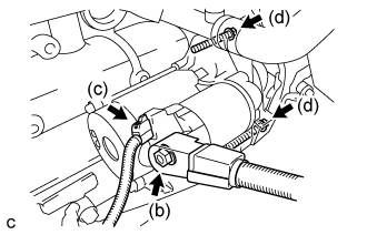
53. REMOVE STARTER ASSEMBLY (for 1.6 kW Type)

  1. A102709E01
    Remove the 2 bolts, then remove the ground cable and bracket.

  1. A113538E02
    Remove the nut and disconnect the wire harness from terminal 30.

  1. Disconnect the terminal 50 connector from the starter assembly.

  1. Remove the 2 bolts and the starter assembly.


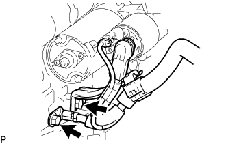
54. REMOVE STARTER ASSEMBLY (for 1.7 kW Type)

  1. A282585
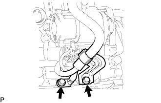
    Remove the 2 bolts, then disconnect the ground cable and wiring harness clamp bracket.

  1. A282586
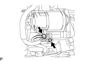
    Open the terminal cap.

  1. Disconnect the starter connector.
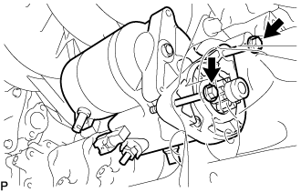
  1. Remove the nut and disconnect the starter wire.
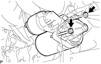
  1. A282587
    Remove the 2 bolts and starter assembly.


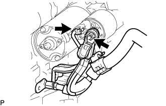
55. REMOVE STARTER ASSEMBLY (for 2.0 kW Type)

  1. A282589
    Remove the 2 bolts, then disconnect the ground cable and wiring harness clamp bracket.

  1. A282590
    Open the terminal cap.

  1. Remove the nut, and then disconnect the starter wire harness.

  1. Disconnect the starter connector.

  1. A282591
    Remove the 2 bolts and starter assembly.


56. REMOVE MANUAL TRANSMISSION UNIT ASSEMBLY (for Manual Transmission)
(Click here)

57. REMOVE AUTOMATIC TRANSMISSION ASSEMBLY (for Automatic Transmission)
(Click here)

58. REMOVE CLUTCH COVER ASSEMBLY (for Manual Transmission)

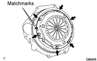
  1. C114267E01
    Put matchmarks on the clutch cover assembly and the flywheel sub-assembly.

  1. Loosen each set bolt one turn at a time until spring tension is released.

  1. Remove the set bolts, and pull off the clutch cover assembly.

    NOTICE:
    Do not drop the clutch disc assembly.


59. REMOVE CLUTCH DISC ASSEMBLY (for Manual Transmission)

NOTICE:
Keep the lining part of the clutch disc assembly, the pressure plate and surface of the flywheel sub-assembly away from oil and foreign matter.


60. REMOVE FLYWHEEL SUB-ASSEMBLY (for Manual Transmission)

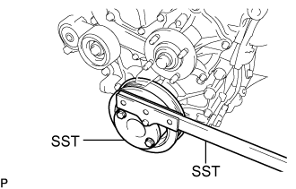
  1. A102137E01
    Fix the crankshaft with SST.
    SST
    09213-54015   (91651-60855)
    09330-00021  

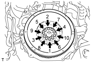
  1. A109815E02
    Remove the 10 bolts and flywheel.


61. REMOVE DRIVE PLATE AND RING GEAR SUB-ASSEMBLY (for Automatic Transmission)

  1. A102137E01
    Fix the crankshaft with SST.
    SST
    09213-54015   (91651-60855)
    09330-00021  

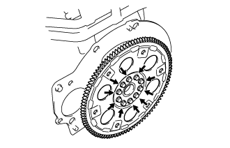
  1. A102156E01
    Remove the 10 bolts, spacer RR, drive plate and spacer FR.


62. REMOVE REAR END PLATE
  1. Remove the 2 bolts and rear end plate.


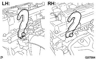
63. INSTALL ENGINE HANGERS

  1. G037564E02
    Install the engine hangers with the bolts.

    Torque:
    42 N*m{ 428 kgf*cm , 30 ft.*lbf }

    HINT:
    Engine Hangers
    12281-75040
    Bolt
    91552-A1020

    NOTICE:
    Use new bolts for the engine hangers.


64. REMOVE FRONT SUSPENSION CROSS MEMBER SUB-ASSEMBLY
  1. Hold the engine with the engine sling device and chain block.

  1. Remove the 4 bolts from the engine mounting insulator.

  1. Remove the engine assembly by operating the engine sling device and chain block.


65. INSTALL ENGINE STAND

66. REMOVE ENGINE WIRE
  1. Remove the engine wire from the engine assembly.


67. REMOVE VENTILATION PIPE
  1. Remove the bolt and ventilation pipe.


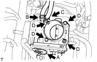
68. REMOVE THROTTLE BODY ASSEMBLY

  1. A102438E01
    Disconnect the throttle motor connector. (A)

  1. Slide the clamp and disconnect the water by-pass hose. (B)

  1. Slide the clamp and disconnect the No. 2 water by-pass hose. (C)

  1. for Type A:
    Remove the 2 bolts and 2 nuts, and then remove the throttle body assembly. (D)

  1. for Type B:
    Remove the 4 bolts and throttle body assembly. (D)

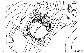
  1. G037700
    Remove the gasket from the intake manifold.


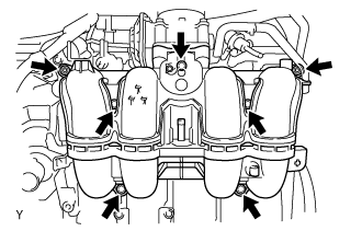
69. REMOVE INTAKE MANIFOLD
  1. Disconnect the ventilation hose No.3.

  1. A102806E01
    Remove the 5 bolts, 2 nuts, intake manifold and gasket.


70. REMOVE IGNITION COIL ASSEMBLY
  1. Remove the bolts and ignition coil assembly.


71. REMOVE SPARK PLUG

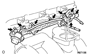
72. REMOVE FUEL DELIVERY PIPE SUB-ASSEMBLY

NOTICE:
Be careful not to drop the injectors when removing the delivery pipe.

  1. A087156
    Disconnect the fuel hoses.

  1. Disconnect the 4 injector connectors.

  1. Remove the 2 bolts O-ring and fuel pulsation damper assembly.

  1. Remove the 2 bolts and delivery pipe together with the 4 injectors.

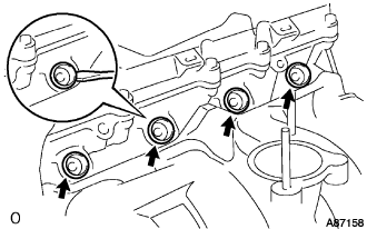
  1. Remove the delivery pipe spacers.

  1. A087158
    Using a screwdriver, pry out the 4 spacers from the cylinder head.


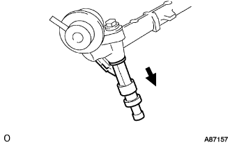
73. REMOVE INJECTOR ASSEMBLY

  1. A087157E01
    Pull out the 4 injectors from the delivery pipe.

  1. Remove the O-rings from the injectors.


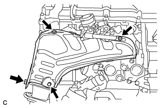
74. REMOVE EXHAUST MANIFOLD HEAT INSULATOR NO.1

  1. A113523
    Remove the 4 bolts and the heat insulator No.1.


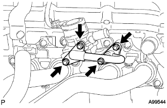
75. REMOVE INTAKE PIPE NO.4 (w/ Secondary Air Injection System)

  1. A099544E02
    Remove the 4 nuts and intake pipe No.4.

  1. Remove the 2 gaskets.


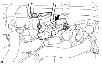
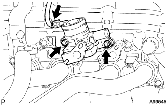
76. REMOVE AIR SWITCHING VALVE ASSEMBLY (w/ Secondary Air Injection Ststem)

  1. A264866E01
    w/ Manifold Absolute Pressure Sensor:
    Disconnect the vacuum hose from the air switching valve assembly.

  1. A099545E02
    Disconnect the connector.

  1. Remove the 2 nuts and the switching valve.


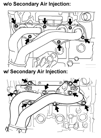
77. REMOVE EXHAUST MANIFOLD

  1. A112543E02
    w/o Secondary air injection system:

    1. Remove the 6 nuts, exhaust manifold and gasket.

  1. w/ Secondary air injection system:

    1. Remove the 8 nuts, exhaust manifold and gasket.


78. REMOVE FAN PULLEY
  1. Remove the 4 nuts, fan pulley and fan spacer.


79. REMOVE WATER BY-PASS PIPE NO.1
  1. Remove the bolt, 2 nuts, water by-pass pipe and gasket.


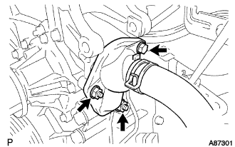
80. REMOVE WATER INLET

  1. A087301
    Remove the 2 nuts, bolt, water inlet and gasket.


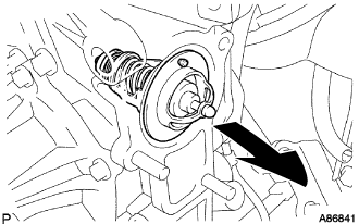
81. REMOVE THERMOSTAT

  1. A086841J01
    Remove the thermostat.


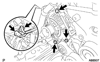
82. REMOVE GENERATOR ASSEMBLY

  1. A088507
    Disconnect the generator connector.

  1. Remove the terminal cap.

  1. Remove the nut and disconnect the wire harness from terminal B.

  1. Remove the 3 bolts and generator assembly.


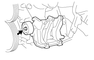
83. REMOVE IDLE PULLEY ASSEMBLY (w/ Air Conditioning System)

  1. A332600
    Loosen the bolt, and then remove the idle pulley assembly.

    HINT:
    The bolt in the illustration cannot be removed from the idle pulley assembly.


84. REMOVE COMPRESSOR MOUNTING BRACKET NO.1 (w/ Air Conditioning System)

  1. A337819
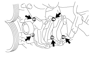
    Remove the 5 bolts and compressor mounting bracket No.1.


85. REMOVE IDLER PULLEY SUB-ASSEMBLY NO.1

  1. A102170
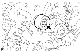
    Remove the bolt, pulley plate, collar, and idler pulley sub-assembly No.1.


86. REMOVE V-RIBBED BELT TENSIONER ASSEMBLY

  1. A232341
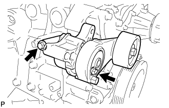
    Remove the 2 bolts and belt tensioner.


87. REMOVE ENGINE OIL PRESSURE SWITCH ASSEMBLY

  1. A102133
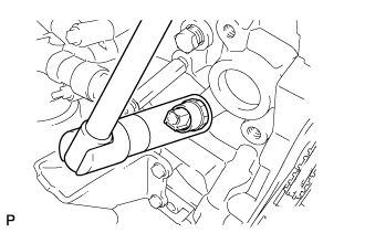
    Using a 24 mm deep socket wrench, remove the oil pressure switch.


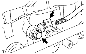
88. REMOVE KNOCK CONTROL SENSOR

  1. G037712E01
    Disconnect the knock control sensor connector.

  1. Remove the bolt and the knock control sensor.


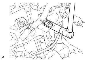
89. REMOVE WATER TEMPERATURE SENSOR

  1. A102134
    Using a 19 mm deep socket wrench, remove the water temperature sensor.


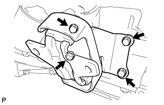
90. REMOVE ENGINE MOUNTING BRACKET FRONT NO.1 RH

  1. A102168
    Remove the 4 bolts and mounting bracket.


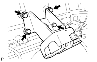
91. REMOVE ENGINE MOUNTING BRACKET FRONT NO.1 LH

  1. A102169
    Remove the 4 bolts and mounting bracket.


92. REMOVE ENGINE OIL LEVEL SENSOR
  1. Remove the 4 bolts and engine oil level sensor.

← COMPONENTS (from Oct 2014)REMOVAL (from Jan 2017) →