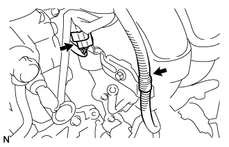
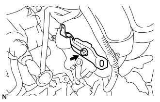
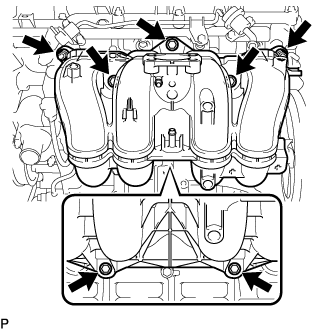
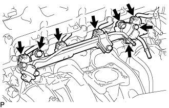
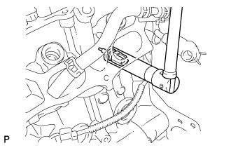
As the engine assembly with transmission is extremely heavy, the engine lifter may suddenly drop if the instructions listed in the repair manual are not followed. Therefore, always follow the instructions listed in the repair manual when performing this procedure.
After turning the ignition switch off, waiting time may be required before disconnecting the cable from the battery terminal. Therefore, make sure to read the disconnecting the cable from the battery terminal notice before proceeding with work (Click here).
3.
DISCONNECT CABLE FROM NEGATIVE BATTERY TERMINAL
NOTICE:
When disconnecting the cable, some systems need to be initialized after the cable is reconnected (Click here).
4.
REMOVE NO. 1 ENGINE UNDER COVER
5.
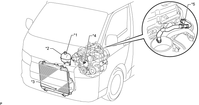
DRAIN ENGINE COOLANT
CAUTION:
Do not remove the radiator reservoir cap sub-assembly while the engine and radiator are still hot. Pressurized, hot engine coolant and steam may be released and cause serious burns.
HINT:
Collect the engine coolant in a container and dispose of it according to the local regulations.
Loosen the radiator drain cock plug and drain the engine coolant.
Text in Illustration
*1
Radiator Reservoir Cap Sub-assembly
*2
Radiator Reservoir Assembly
*3
Radiator Drain Cock Plug
*4
Cylinder Block Water Drain Cock Plug
*5
2-Way
-
-
Remove the radiator reservoir cap sub-assembly.
Loosen the cylinder block water drain cock plug and drain the engine coolant from the engine.
6.
DRAIN ENGINE OIL
Remove the oil filler cap.
Remove the oil pan drain plug and gasket, and then drain the engine oil into a container.
NOTICE:
Collect the oil in a disposable oil container.
Clean the oil pan drain plug and install it with a new gasket.
9.
REMOVE ENGINE SERVICE HOLE SUB COVER SUB-ASSEMBLY
Roll up the carpet, and remove the 5 bolts and engine service hole sub cover sub-assembly.
10.
REMOVE FAN AND GENERATOR V BELT
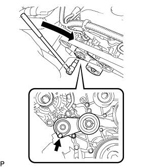
Use the hexagon-shaped part indicated by the arrow in the illustration to move the tensioner pulley downward and decrease the tension in the fan and generator V belt. Then remove the fan and generator V belt.
NOTICE:
When removing the fan and generator V belt, do not use the bolt of the idle pulley.
HINT:
After removing the fan and generator V belt, move the tensioner upward to the maximum amount.
11.
DISCONNECT NO. 4 RADIATOR HOSE
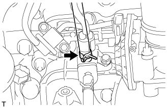
Slide the clamp and disconnect the No. 4 radiator hose from the engine.
12.
DISCONNECT NO. 2 RADIATOR HOSE
Slide the clamp and disconnect the No. 2 radiator hose from the No. 1 radiator pipe.
13.
DISCONNECT INLET HEATER WATER HOSE A
Slide the clamp and disconnect the inlet heater water hose A from the heater unit.
14.
DISCONNECT OUTLET HEATER WATER HOSE B
Slide the clamp and disconnect the outlet heater water hose B from the heater unit.
15.
DISCONNECT FUEL VAPOR FEED HOSE ASSEMBLY
Slide the clamp and disconnect the fuel vapor feed hose from the purge VSV.
16.
DISCONNECT UNION TO CONNECTOR TUBE HOSE
Slide the clamp and disconnect the union to connector tube hose from the intake manifold.
17.
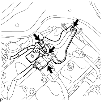
REMOVE AIR PRESSURE SENSOR
Disconnect the air pressure sensor connector.
Disconnect the vacuum hose.
Detach the wire harness clamp.
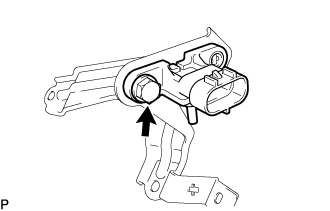
Remove the 2 bolts and air pressure sensor together with the bracket.
Remove the bolt and air pressure sensor.
18.
REMOVE INTAKE AIR CONNECTOR
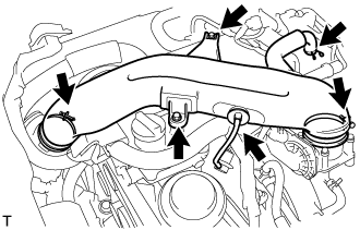
Slide the clamp and disconnect the No. 2 PCV hose from the cylinder head cover sub-assembly.
Disconnect the vacuum hose from the intake air connector.
Loosen the 2 hose clamps.
Remove the 2 bolts and intake air connector.
19.
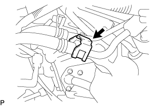
DISCONNECT NO. 5 AIR HOSE
Slide the clamp and disconnect the No. 5 air hose from the air switching valve assembly.
20.
DISCONNECT NO. 1 FUEL HOSE
Disconnect the No. 1 fuel hose from the fuel pressure pulsation damper assembly (Click here).
21.
DISCONNECT NO. 2 FUEL HOSE
Disconnect the No. 2 fuel hose from the fuel delivery pipe sub-assembly (Click here).
22.
DISCONNECT VANE PUMP ASSEMBLY
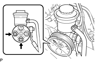
Disconnect the oil pressure switch connector.
Remove the 2 bolts and disconnect the vane pump assembly from the engine.
Support the vane pump assembly securely.
23.
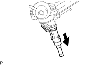
REMOVE ENGINE OIL LEVEL DIPSTICK
24.
REMOVE ENGINE OIL LEVEL DIPSTICK GUIDE
Remove the bolt and engine oil level dipstick guide.
25.
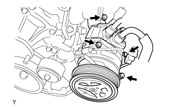
DISCONNECT COMPRESSOR AND MAGNETIC CLUTCH
Disconnect the compressor and magnetic clutch connector.
Remove the 4 bolts and disconnect the compressor and magnetic clutch from the engine.
HINT:
Disconnect the compressor and magnetic clutch with the No. 1 cooler refrigerant suction hose and No. 1 cooler refrigerant discharge hose stuck by suspended from the rope.
Support the compressor and magnetic clutch securely.
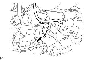
26.
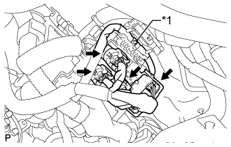
DISCONNECT ENGINE WIRE
Disconnect the wire harness support of the ECM.
Disconnect the connectors of the ECM.
Disconnect the clamps of the engine wire and ground cable.
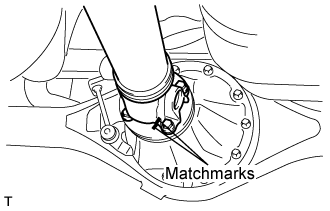
If the flange connection is hard to separate, temporarily tighten one nut only and evenly tap the flange with a brass bar and hammer to separate the propeller shaft assembly from the differential companion flange.
Remove the propeller shaft assembly.
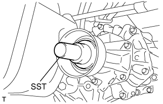
Insert SST in the transmission to prevent oil leakage.
NOTICE:
Do not damage the oil seal.
Use the following SST for the automatic transmission
SST
09325-40010
Use the following SST for the manual transmission
SST
09325-20010
29.
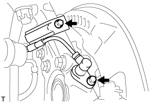
REMOVE FRONT SPEED SENSOR LH
Remove the 2 bolts, and separate the speed sensor from the steering knuckle.
NOTICE:
Be careful not to damage the speed sensor.
Prevent foreign matter from adhering to the speed sensor.
30.
REMOVE FRONT SPEED SENSOR RH
HINT:
Use the same procedure described for the LH side.
31.
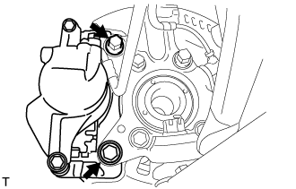
REMOVE FRONT DISC BRAKE CALIPER ASSEMBLY LH
Remove the 2 bolts, and disconnect the brake caliper assembly.
NOTICE:
Use a wire or an equivalent to keep the brake caliper from hanging down by the flexible hose.
32.
REMOVE FRONT DISC BRAKE CALIPER ASSEMBLY RH
HINT:
Use the same procedure described for the LH side.
33.
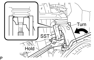
SEPARATE FRONT SUSPENSION SUB-ASSEMBLY UPPER LH
Remove the cotter pin and loosen the nut.
SST
09628-62011
NOTICE:
Do not remove the nut.
Using SST, separate the steering knuckle from the suspension upper arm and remove the nut.
NOTICE:
Fix the steering knuckle with a wire so that the flexible hose does not receive excessive force.
Do not damage the ball joint dust cover.
34.
SEPARATE FRONT SUSPENSION SUB-ASSEMBLY UPPER RH
HINT:
Use the same procedure described for the LH side.
35.
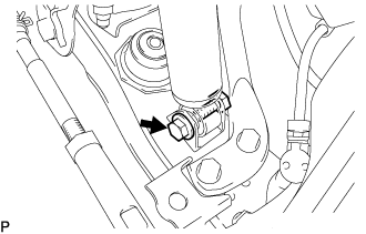
SEPARATE FRONT SHOCK ABSORBER ASSEMBLY LH
Remove the bolt and separate the front shock absorber from the front suspension lower arm.
36.
SEPARATE FRONT SHOCK ABSORBER ASSEMBLY RH
HINT:
Use the same procedure described for the LH side.
37.
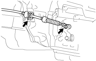
DISCONNECT TRANSMISSION CONTROL CABLE ASSEMBLY
Move the shift lever to N.
Remove the nut and disconnect the transmission control cable assembly from the transmission control shaft lever LH.
Remove the clip and disconnect the transmission control cable assembly from the transmission control cable bracket.
38.
DISCONNECT OIL COOLER HOSE
Slide the 2 clamps and disconnect the inlet oil cooler hose and outlet oil cooler hose from the oil cooler tube.
39.
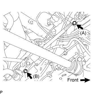
SEPARATE STEERING TORQUE SHAFT ASSEMBLY
Loosen bolt (A) and remove bolt (B), then slide the steering torque shaft assembly.
HINT:
Do not remove bolt (A).
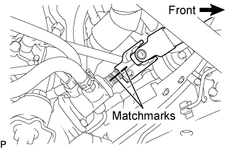
Do not disconnect the steering torque shaft assembly from the power steering link assembly.
Put matchmarks on the steering torque shaft assembly and the power steering link assembly.
Separate the steering torque shaft assembly from the power steering link assembly.
40.
REMOVE ENGINE ASSEMBLY WITH TRANSMISSION
Using the engine lifter, hold the engine assembly and separate the rear engine mount.
NOTICE:
Place wooden blocks or plate lift attachments so that the engine is level.
With the exception of installing the engine assembly to an engine stand or removing the engine assembly from an engine stand, do not perform any work on the engine while it is suspended, as doing so is dangerous.
Never install attachments to the oil pan of the engine assembly or transmission as doing so may deform the oil pan.
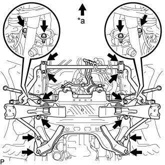
Remove the stabilizer brackets and 16 bolts of the front suspension crossmember sub-assembly.
Text in Illustration
*a
Front Side
Operate the engine lifter, and then slowly remove the engine from the vehicle.
NOTICE:
Make sure the engine is clear of all wiring and hoses.
While lowering the engine from the vehicle, do not allow it to contact the vehicle.
Attach an engine sling device and hang the engine with a chain block.
NOTICE:
Pay attention to the angle of the sling device as the engine assembly or engine hangers may be damaged or deformed if the angle is incorrect.
41.
INSTALL ENGINE HANGER
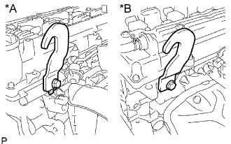
Install the 2 engine hangers with the 2 bolts.
Torque:
42 N*m{
428 kgf*cm
, 31 ft.*lbf
}
Text in Illustration
*A
LH Side
*B
RH Side
NOTICE:
Use new 2 bolts for the 2 engine hangers.
HINT:
Engine Hangers
12281-75050
Bolt
91672-81025
42.
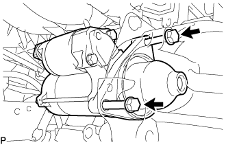
REMOVE STARTER ASSEMBLY
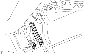
Detach the wire harness clamp from the wire harness bracket.
Using wooden blocks or plate lift attachments, set the engine on a flat surface.
NOTICE:
Place wooden blocks or plate lift attachments so that the engine is level.
Never install attachments to the oil pan of the engine assembly or transmission as doing so may deform the oil pan.
Perform this step while supporting the engine assembly using a sling device and chain block.
45.
REMOVE DRIVE PLATE AND RING GEAR SUB-ASSEMBLY
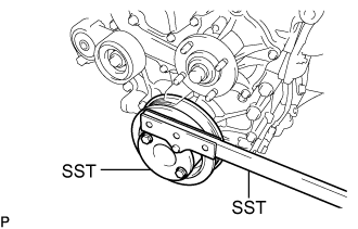
Using SST, hold the crankshaft.
SST
09213-54015
(91651-60855)
09330-00021
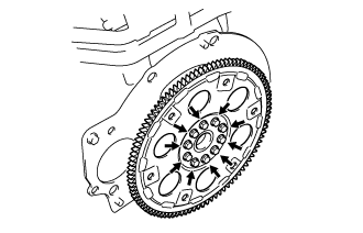
Remove the 10 bolts, rear drive plate spacer, drive plate and ring gear sub-assembly and front drive plate spacer.
46.
REMOVE REAR END PLATE
Remove the bolt and disconnect the No. 1 water by-pass pipe from rear end plate.
Remove the bolt and rear end plate.
47.
REMOVE FRONT SUSPENSION CROSSMEMBER SUB-ASSEMBLY
Hold the engine with the engine sling device and chain block.
Remove the 4 bolts from the engine mounting insulator.
Remove the engine assembly by operating the engine sling device and chain block.
48.
REMOVE ENGINE WIRE
Remove the engine wire from the engine assembly.
49.
INSTALL ENGINE TO ENGINE STAND
NOTICE:
Pay attention to the angle of the sling device as the engine assembly or engine hangers may be damaged or deformed if the angle is incorrect.
With the exception of installing the engine assembly to an engine stand or removing the engine assembly from an engine stand, do not perform any work on the engine while it is suspended, as doing so is dangerous.
Install the engine to an engine stand with the bolts.
Remove the 2 bolts and 2 engine hangers.
50.
REMOVE PCV PIPE
Remove the bolt and PCV pipe.
51.
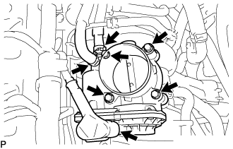
REMOVE THROTTLE BODY ASSEMBLY
Disconnect the throttle motor connector.
Slide the clamp and disconnect the water by-pass hose from the throttle body assembly.
Slide the clamp and disconnect the No. 2 water by-pass hose from the throttle body assembly.
Remove the 4 bolts and throttle body assembly.
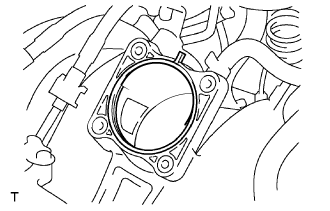
Remove the gasket from the intake manifold.
52.
REMOVE INTAKE MANIFOLD
Disconnect the vacuum switching valve connector.
Slide the clamp and disconnect the purge line hose from the vacuum switching valve.
Detach the 2 wire harness clamps from the wire harness bracket.
Slide the clamp and disconnect the No. 3 PCV hose from the intake manifold.
Slide the clamp and disconnect the vacuum hose from the intake manifold.
Remove the bolt and wire harness bracket from the intake manifold.
Remove the 5 bolts, 2 nuts and intake manifold.
Remove the gasket from the intake manifold.
Remove the intake manifold insulator from the intake manifold.
53.
REMOVE IGNITION COIL ASSEMBLY
Remove the 4 bolts and 4 ignition coil assemblies.
54.
REMOVE SPARK PLUG
Using a 16 mm spark plug wrench, remove the 4 spark plugs.
55.
REMOVE FUEL DELIVERY PIPE SUB-ASSEMBLY
NOTICE:
Be careful not to drop the fuel injector assemblies when removing the fuel delivery pipe sub-assembly.
Disconnect the vacuum hose from the fuel pressure regulator assembly.
Slide the clamp and disconnect the No. 2 fuel hose from the fuel pressure regulator assembly.
Disconnect the 4 fuel injector connectors.
Remove the 2 bolts, fuel pressure pulsation damper assembly and O-ring.
Remove the 2 bolts and fuel delivery pipe sub-assembly together with the 4 fuel injector assemblies.
NOTICE:
Be careful not to drop the fuel injector assemblies when removing the fuel delivery pipe sub-assembly.
Remove the 2 No. 1 delivery pipe spacers from the cylinder head sub-assembly.
Remove the 4 injector vibration insulators.
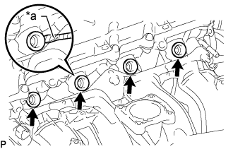
Using a screwdriver, pry out the 4 injector spacers and 4 O-rings from the cylinder head sub-assembly.
Text in Illustration
*a
Protective Tape
HINT:
Tape the screwdriver tip before use.
56.
REMOVE FUEL INJECTOR ASSEMBLY
Pull out the 4 fuel injector assemblies from the fuel delivery pipe sub-assembly.
Text in Illustration
Pull Out
Remove the O-rings from the fuel injector assemblies.
57.
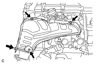
REMOVE NO. 1 EXHAUST MANIFOLD HEAT INSULATOR
Remove the 4 bolts and No. 1 exhaust manifold heat insulator.
58.
REMOVE NO. 4 INTAKE PIPE
Remove the 4 nuts and No. 4 intake pipe.
Remove the 2 gaskets.
59.
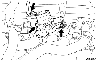
REMOVE AIR SWITCHING VALVE ASSEMBLY
Disconnect the air switching valve connector.
Remove the 2 nuts and air switching valve assembly.
60.
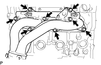
REMOVE EXHAUST MANIFOLD
Remove the 8 nuts, exhaust manifold and gasket.
61.
REMOVE FAN PULLEY
Remove the 4 nuts, fan pulley and fan spacer.
62.
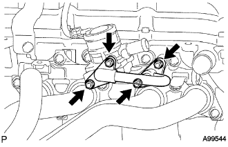
REMOVE NO. 1 WATER BY-PASS PIPE
Remove the bolt, 2 nuts, No. 1 water by-pass pipe and gasket.
63.
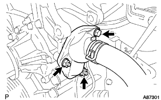
REMOVE WATER INLET
Remove the 2 nuts and bolt and disconnect the water inlet.
Remove the gasket.
64.
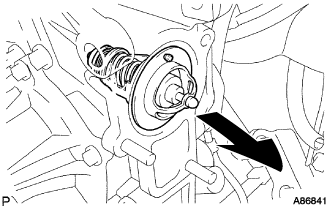
REMOVE THERMOSTAT
Remove the thermostat and gasket.
65.
REMOVE GENERATOR ASSEMBLY
Disconnect the generator connector.
Remove the terminal cap.
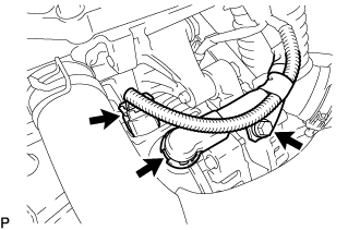
Remove the nut and disconnect the wire harness from terminal B.
Remove the bolt and disconnect the wire harness clamp.
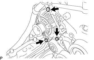
Remove the 3 bolts and generator assembly.
66.
REMOVE IDLE PULLEY ASSEMBLY
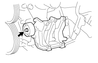
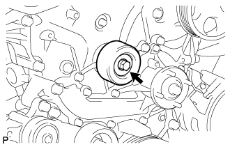
Loosen the bolt, and then remove the idle pulley assembly.
HINT:
The bolt in the illustration cannot be removed from the idle pulley assembly.
67.
REMOVE NO. 1 COMPRESSOR MOUNTING BRACKET
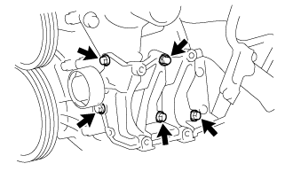
Remove the 5 bolts and No. 1 compressor mounting bracket.
68.
REMOVE NO. 1 IDLER PULLEY SUB-ASSEMBLY
Remove the bolt, collar and No. 1 idler pulley sub-assembly.
69.
REMOVE V-RIBBED BELT TENSIONER ASSEMBLY
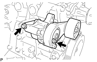
Remove the 2 bolts and V-ribbed belt tensioner assembly.
70.
REMOVE ENGINE OIL PRESSURE SWITCH ASSEMBLY
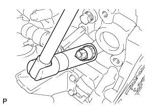
Using a 24 mm deep socket wrench, remove the engine oil pressure switch assembly.
71.
REMOVE KNOCK CONTROL SENSOR
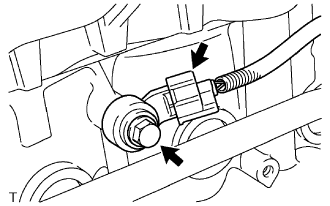
Disconnect the knock control sensor connector.
Remove the bolt and knock control sensor.
72.
REMOVE ENGINE COOLANT TEMPERATURE SENSOR
Disconnect the engine coolant temperature sensor connector.
Using a 19 mm deep socket wrench, remove the engine coolant temperature sensor and gasket.
73.
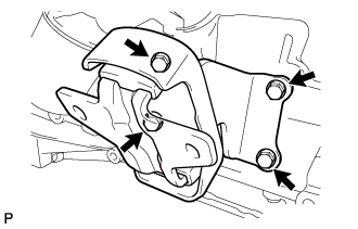
REMOVE FRONT NO. 1 ENGINE MOUNTING BRACKET RH
HINT:
Perform this procedure only when replacement of the front No. 1 engine mounting bracket RH is necessary.
Remove the 4 bolts and front No. 1 engine mounting bracket RH.
74.
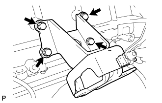
REMOVE FRONT NO. 1 ENGINE MOUNTING BRACKET LH
HINT:
Perform this procedure only when replacement of the front No. 1 engine mounting bracket LH is necessary.
Remove the 4 bolts and front No. 1 engine mounting bracket LH.