Removal / installation · Vehicles built Oct 2014 – Dec 2016
Versions by build date: Oct 2014 – Dec 2016from Jan 2017
1.
PLACE FRONT WHEELS FACING STRAIGHT AHEAD
2.
DISCONNECT CABLE FROM NEGATIVE BATTERY TERMINAL
3.
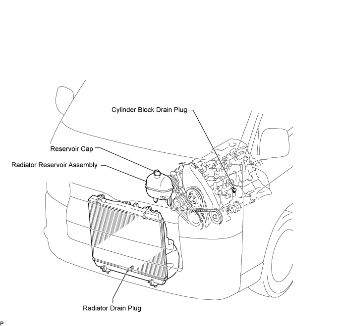
DRAIN ENGINE COOLANT
CAUTION:
To avoid the danger of being burned, do not remove the reservoir cap while the engine and radiator assembly are still hot. Thermal expansion will cause hot engine coolant and steam to blow out from the radiator assembly.
Loosen the radiator drain plug.
Remove the reservoir cap.
Loosen the cylinder block drain plug and drain the coolant.
Tighten the radiator drain plug.
Tighten the cylinder block drain plug.
Torque:
13 N*m{
130 kgf*cm
, 9 ft.*lbf
}
4.
DRAIN ENGINE OIL
NOTICE:
Prolonged and repeated contact with mineral oil will result in the removal of natural fats from the skin, leading to dryness, irritation and dermatitis. In addition, used engine oil contains potentially harmful contaminants which may cause skin cancer.
Exercise caution in order to minimize the duration and frequency of skin contact with used oil. Wear protective clothing and gloves. Wash your skin thoroughly with soap and water, or use water-less hand cleaner to remove any used engine oil. Do not use gasoline, thinners, or solvents.
In order to preserve the environment, used oil and the used oil filter must be disposed of only at designated disposal sites.
Remove the oil filler cap.
Remove the oil drain plug, and drain the oil into a container.
Clean the drain plug, and install it with a new gasket.
Torque:
35 N*m{
350 kgf*cm
, 25 ft.*lbf
}
5.
REMOVE FRONT SEAT ASSEMBLY RH (for Hi-back Seat Type)
HINT:
Use the same procedures described for the LH side. (Click here)
6.
REMOVE FRONT SEAT ASSEMBLY RH (for Low-back Seat Type)
HINT:
Use the same procedures described for the LH side. (Click here)
7.
REMOVE FRONT DOOR SCUFF PLATE RH
8.
REMOVE ENGINE SERVICE HOLE SUB COVER SUB-ASSEMBLY
Turn back the carpet, and remove the engine service hole cover sub-assembly.
9.
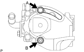
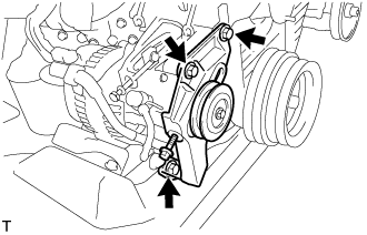
REMOVE VANE PUMP V BELT
Loosen the bolt A and nut B, and remove the V belt.
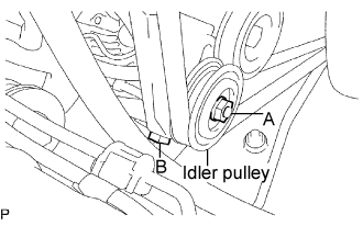
10.
REMOVE V (COOLER COMPRESSOR TO CRANKSHAFT PULLEY) BELT NO.1 (W/ AIR CONDITIONING)
Loosen the nut A and bolt B, and remove the V belt.
11.
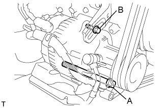
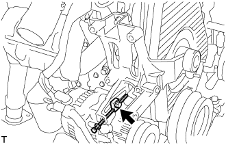
REMOVE FAN & GENERATOR V BELT (w/o Air Conditioning)
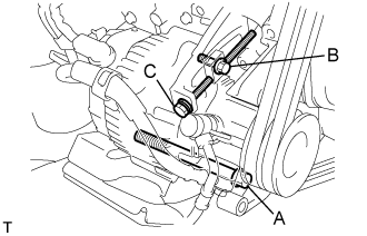
Loosen the bolts A and B, and remove the V belt.
12.
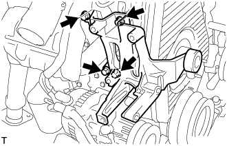
REMOVE FAN & GENERATOR V BELT (w/ Air Conditioning)
Loosen the bolts A and B.
Loosen the adjusting bolt C, and remove the V belt.
13.
DISCONNECT RADIATOR HOSE INLET
14.
DISCONNECT RADIATOR HOSE NO.4
15.
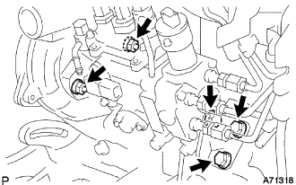
DISCONNECT INJECTION PUMP TO FUEL FILTER FUEL HOSE OR PIPE
16.
SEPARATE AIR CLEANER HOSE NO.2
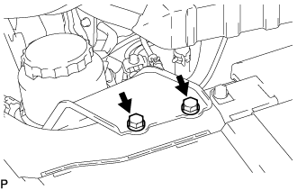
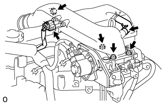
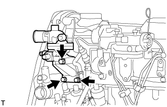
Loosen the bolt, and disconnect the air cleaner hose No.2.
Disconnect the clamp and ground cable of the engine wire.
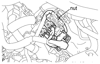
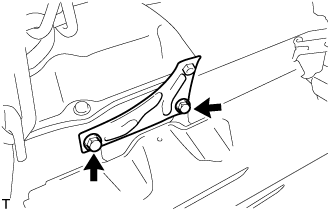
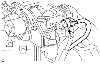
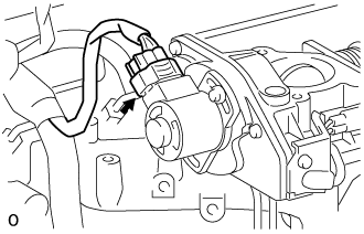
Remove the nut then remove the starter wire harness.
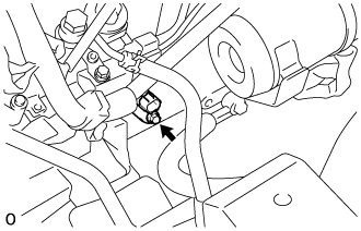
Remove the connector and nut, as shown the illustration.
20.
REMOVE EXHAUST PIPE SUB-ASSEMBLY FRONT NO.2 (for Long Wheelbase)
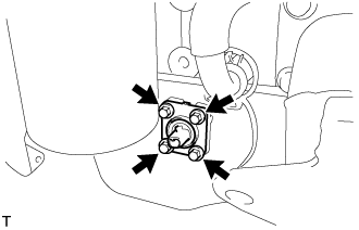
Remove the 4 bolts, 2 compression springs.
Disconnect the exhaust pipe support, and remove the exhaust pipe assembly front No.2 and 2 gaskets.
21.
REMOVE EXHAUST PIPE SUB-ASSEMBLY FRONT NO.2 (for Super Long Wheelbase)
Remove the 4 bolts, 2 nuts, 2 compression springs.
Disconnect the exhaust pipe support, and remove the exhaust pipe assembly front No.2 and 2 gaskets.
22.
REMOVE EXHAUST PIPE SUB-ASSEMBLY FRONT NO.1 (for Long Wheelbase)
Loosen the clamp bolt, and separate the exhaust pipe support bracket No.1 from the exhaust pipe sub-assembly front No.1.
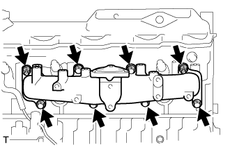
Remove the 3 bolts, exhaust pipe sub-assembly front No.1 and gasket from the exhaust manifold.
23.
REMOVE EXHAUST PIPE SUB-ASSEMBLY FRONT NO.1 (for Super Long Wheelbase)
Loosen the clamp bolt, and separate the exhaust pipe support bracket No.1 from the exhaust pipe sub-assembly front No.1.
Remove the 3 bolts, exhaust pipe sub-assembly front No.1 and gasket from the exhaust manifold.
24.
REMOVE PROPELLER SHAFT ASSEMBLY (for Long Wheelbase)
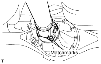
Put matchmarks on both flanges.
Remove the 4 nuts, bolts and washers.
HINT:
If the flange connection is hard to separate, temporarily tighten one nut only and evenly tap the flange with a brass bar and hammer to separate the propeller shaft assembly from the differential companion flange.
Remove the propeller shaft assembly.
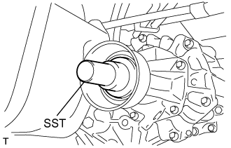
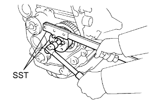
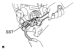
Insert SST in the transmission to prevent oil leakage.
NOTICE:
Do not damage the oil seal.
Use the following SST for the automatic transmission
SST
09325-40010
Use the following SST for the manual transmission
SST
09325-20010
25.
REMOVE PROPELLER SHAFT ASSEMBLY (for Super Long Wheelbase)
Put matchmarks on both flanges.
Remove the 4 nuts, bolts and washers.
HINT:
If the flange connection is hard to separate, temporarily tighten one nut only and evenly tap the flange with a brass bar and hammer to separate the propeller with center bearing shaft assembly from the differential companion flange.
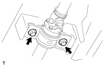
Remove the 2 bolts and center support bearing assembly No.1.
Remove the propeller with center bearing shaft assembly.
Insert SST in the transmission to prevent oil leakage.
NOTICE:
Do not damage the oil seal.
Use the following SST for the automatic transmission.
SST
09325-40010
Use the following SST for the manual transmission.
SST
09325-20010
26.
SEPARATE SPEED SENSOR FRONT LH (w/ ABS)
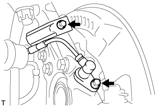
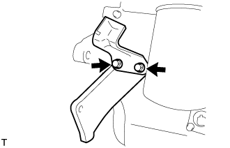
Remove the 2 bolts, and separate the speed sensor from the steering knuckle.
NOTICE:
Be careful not to damage the speed sensor.
Prevent foreign matter from adhering to the speed sensor.
27.
SEPARATE SPEED SENSOR FRONT RH (w/ ABS)
HINT:
Use the same procedures described for the LH side.
28.
SEPARATE FRONT DISC BRAKE CALIPER ASSEMBLY LH
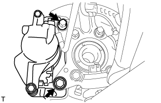
Remove the 2 bolts, and disconnect the brake caliper assembly.
NOTICE:
Use a wire or an equivalent to keep the brake caliper from hanging down by the flexible hose.
29.
SEPARATE FRONT DISC BRAKE CALIPER ASSEMBLY RH
HINT:
Use the same procedures described for the LH side.
30.
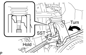
SEPARATE FRONT SUSPENSION ARM SUB-ASSEMBLY UPPER LH
Remove the cotter pin and loosen the nut.
SST
09628-62011
NOTICE:
Do not remove the nut.
Using SST, separate the steering knuckle from the suspension upper arm and remove the nut.
NOTICE:
Fix the steering knuckle with a wire so that the flexible hose does not receive excessive force.
Do not damage the ball joint dust cover.
31.
SEPARATE FRONT SUSPENSION ARM SUB-ASSEMBLY UPPER RH
HINT:
Use the same procedures described for the LH side.
32.
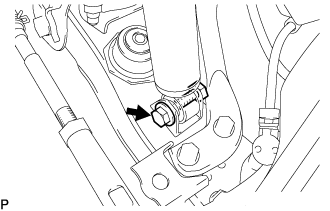
SEPARATE SHOCK ABSORBER ASSEMBLY FRONT LH
Remove the bolt and separate the front shock absorber from the front suspension lower arm.
33.
SEPARATE SHOCK ABSORBER ASSEMBLY FRONT RH
HINT:
Use the same procedures described for the LH side.
34.
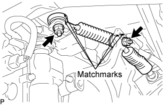
SEPARATE TRANSMISSION CONTROL CABLE ASSEMBLY
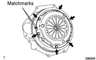
Put matchmarks on the control cable assembly and the outer lever.
Remove the 2 nuts and separate the transmission control cable from the outer lever.
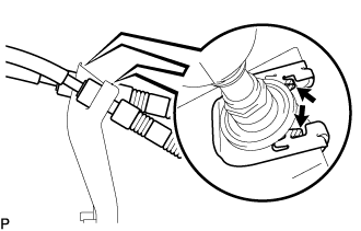
Using a screwdriver, disengage the claws of the 2 clips.
Remove the transmission control cable and 2 clips from the transmission control cable bracket No.1.
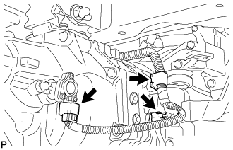
35.
DISCONNECT WIRE HARNESS
Disconnect the 2 connectors and clamp.
36.
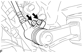
SEPARATE CLUTCH RELEASE CYLINDER ASSEMBLY
Remove the 2 bolts and separate the clutch release cylinder.
37.
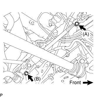
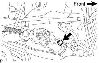
SEPARATE STEERING TORQUE SHAFT ASSEMBLY
Loosen bolt (A) and remove bolt (B), then slide the steering torque shaft assembly.
HINT:
Do not remove bolt (A).
Do not disconnect the steering torque shaft assembly from the power steering link assembly.
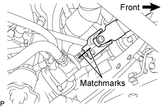
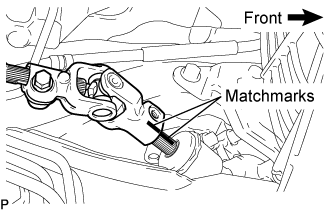
Put matchmarks on the steering torque shaft assembly and the power steering link assembly.
Separate the steering torque shaft assembly from the power steering link assembly.
Remove the bolt and slide the steering torque shaft assembly.
Put matchmarks on the steering torque shaft assembly and the steering bevel gear assembly.
Remove the steering torque shaft assembly from the steering bevel gear assembly.
38.
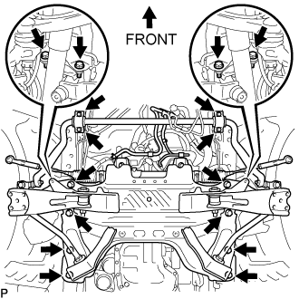
REMOVE ENGINE W/ TRANSMISSION ASSEMBLY
Using the engine lifter, hold the engine assembly and separate the rear engine mounting.
Remove the stabilizer bracket and 16 bolts of the front suspension cross member.
Remove the engine assembly w/ transmission to the vehicle.
39.
REMOVE STARTER ASSEMBLY (for 2.2 kW Type)
Disconnect the starter connector.
Remove the terminal cap.
Remove the nut, and disconnect the 30 terminal.
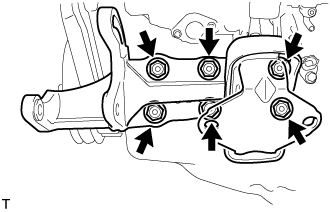
Remove the nut, 2 bolts, and stay.
Remove the nut 2 bolts, and starter assembly.
40.
REMOVE STARTER ASSEMBLY (for 2.7 kW Type)
Disconnect the starter connector.
Remove the terminal cap.
Remove the nut, and disconnect the 30 terminal.
Remove the nut and, 2 bolts, stay and starter assembly.