2014-2019 Hiace · Service Manual ENGINE

REMOVAL

Removal / installation · Vehicles built Apr 2016 – Dec 2016

Versions by build date: Oct 2014 – Dec 2014 Jan 2015 – Mar 2016 Apr 2016 – Dec 2016 from Jan 2017


1. DISCHARGE FUEL SYSTEM PRESSURE
(Click here)

2. PRECAUTION

NOTICE:
After turning the ignition switch off, waiting time may be required before disconnecting the cable from the battery terminal. Therefore, make sure to read the disconnecting the cable from the battery terminal notice before proceeding with work (Click here).


3. DISCONNECT CABLE FROM NEGATIVE BATTERY TERMINAL

NOTICE:
When disconnecting the cable, some systems need to be initialized after the cable is reconnected (Click here).


4. DRAIN ENGINE OIL
  1. Remove the oil filler cap.

  1. Remove the oil pan drain plug and gasket, and then drain the engine oil into a container.

    NOTICE:
    Collect the oil in a disposable oil container.

  1. Clean the oil pan drain plug and install it with a new gasket.

    Torque:
    38 N*m{ 382 kgf*cm , 28 ft.*lbf }


5. DRAIN ENGINE COOLANT

CAUTION:
Do not remove the radiator reservoir cap sub-assembly while the engine and radiator are still hot. Pressurized, hot engine coolant and steam may be released and cause serious burns.

HINT:
Collect the engine coolant in a container and dispose of it according to the local regulations.

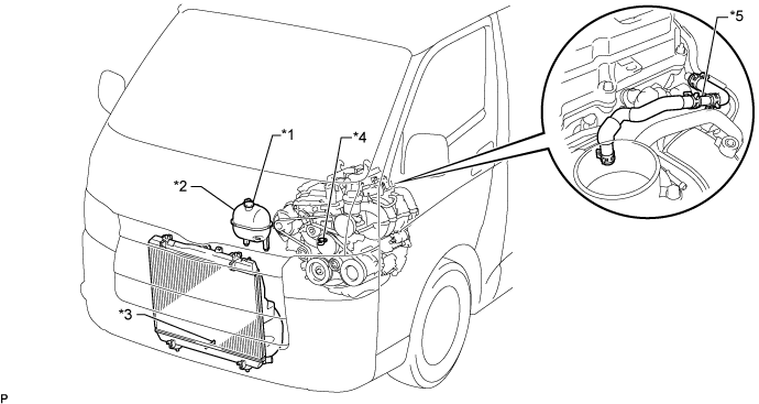
  1. Loosen the radiator drain cock plug and drain the engine coolant.

    A340634E01

    Text in Illustration 
    *1
    Radiator Reservoir Cap Sub-assembly
    *2
    Radiator Reservoir Assembly
    *3
    Radiator Drain Cock Plug
    *4
    Cylinder Block Water Drain Cock Plug
    *5
    2-Way
    -
    -

  1. Remove the radiator reservoir cap sub-assembly.

  1. Loosen the cylinder block water drain cock plug and drain the engine coolant from the engine.


6. REMOVE AUTOMATIC TRANSMISSION
(Click here)

7. DISCONNECT OIL COOLER HOSE
  1. Slide the 2 clamps and disconnect the inlet oil cooler hose and outlet oil cooler hose from the oil cooler tube.


8. DISCONNECT NO. 2 RADIATOR HOSE
  1. Slide the clamp and disconnect the No. 2 radiator hose from the No. 1 radiator pipe.


9. DISCONNECT NO. 4 RADIATOR HOSE
  1. Slide the clamp and disconnect the No. 4 radiator hose from the engine.


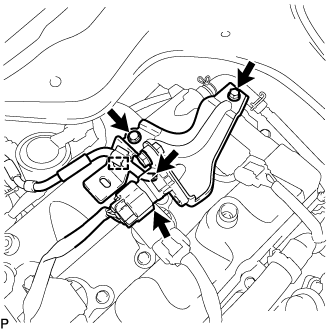
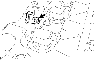
10. REMOVE AIR PRESSURE SENSOR

  1. A337848
    Disconnect the air pressure sensor connector.

  1. Disconnect the vacuum hose.

  1. Detach the wire harness clamp.

  1. Remove the 2 bolts and air pressure sensor together with the bracket.

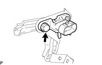
  1. A337849
    Remove the bolt and air pressure sensor.


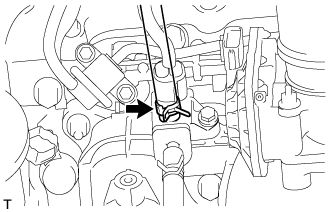
11. DISCONNECT FUEL VAPOR FEED HOSE ASSEMBLY

  1. A340097
    Slide the clamp and disconnect the fuel vapor feed hose from the purge VSV.


12. DISCONNECT UNION TO CONNECTOR TUBE HOSE
  1. Slide the clamp and disconnect the union to connector tube hose from the intake manifold.


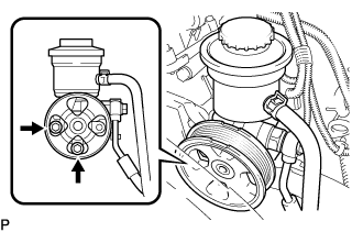
13. DISCONNECT VANE PUMP ASSEMBLY

  1. A102130E01
    Disconnect the oil pressure switch connector.

  1. Remove the 2 bolts and disconnect the vane pump assembly from the engine.

  1. Support the vane pump assembly securely.


14. DISCONNECT ENGINE WIRE
  1. Disconnect the wire harness support of the ECM.

  1. Disconnect the connectors of the ECM.

  1. Disconnect the clamps of the engine wire and ground cable.

  1. Disconnect the starter connector (Click here).

  1. Disconnect the generator connector (Click here).

  1. A101143E05
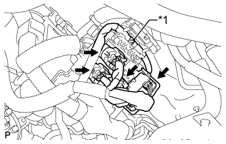
    Remove the nut and disconnect the 4 connectors from the engine room junction block.
    Text in Illustration 
    *1
    Nut


15. REMOVE INTAKE MANIFOLD
(Click here)

16. REMOVE FAN PULLEY
  1. Remove the 4 nuts, fan pulley and fan spacer.


17. REMOVE NO. 1 WATER BY-PASS PIPE
  1. Remove the bolt, 2 nuts, No. 1 water by-pass pipe and gasket.


18. REMOVE GENERATOR ASSEMBLY

  1. A311548
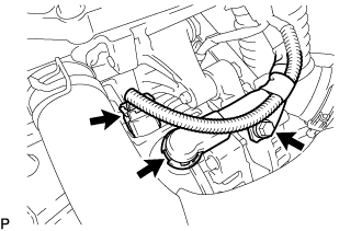
    Disconnect the generator connector.

  1. Remove the terminal cap.

  1. Remove the nut and disconnect the wire harness from terminal B.

  1. Remove the bolt and disconnect the wire harness clamp.

  1. A311549
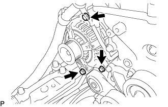
    Remove the 3 bolts and generator assembly.


19. REMOVE CRANKSHAFT POSITION SENSOR
(Click here)

20. REMOVE NO. 1 IDLER PULLEY SUB-ASSEMBLY

  1. A102170
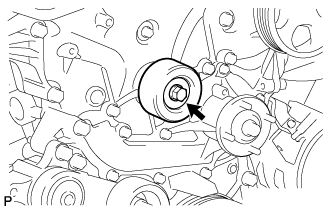
    Remove the bolt, collar and No. 1 idler pulley sub-assembly.


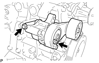
21. REMOVE V-RIBBED BELT TENSIONER ASSEMBLY

  1. A232341
    Remove the 2 bolts and V-ribbed belt tensioner assembly.


22. REMOVE IGNITION COIL ASSEMBLY
  1. Remove the 4 bolts and 4 ignition coil assemblies.


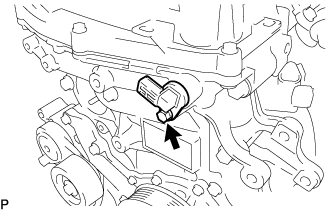
23. REMOVE CAMSHAFT POSITION SENSOR

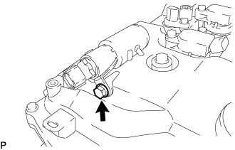
  1. A337859
    for Intake Side:

    1. Disconnect the camshaft position sensor connector.

    2. Remove the bolt and camshaft position sensor.

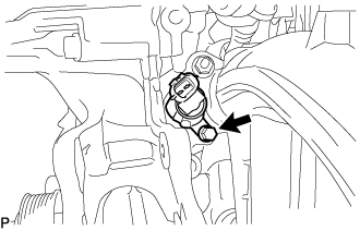
  1. for Exhaust Side:

    1. Disconnect the camshaft position sensor connector.

    2. A337861
      Remove the bolt and camshaft position sensor.


24. REMOVE CAMSHAFT TIMING OIL CONTROL VALVE ASSEMBLY (for Exhaust Side)

  1. for Intake Side:

    1. Disconnect the camshaft timing oil control valve connector.

    2. A337844
      Remove the bolt and camshaft timing oil control valve assembly from the cylinder head sub-assembly.

    3. Remove the O-ring from the camshaft timing oil control valve assembly.

  1. for Exhaust Side:

    1. Disconnect the camshaft timing oil control valve connector.

    2. A337846
      Remove the bolt and camshaft timing oil control valve assembly from the cylinder head cover sub-assembly.

    3. Remove the O-ring from the camshaft timing oil control valve assembly.


25. REMOVE CYLINDER HEAD COVER SUB-ASSEMBLY
  1. Slide the clip and disconnect the PCV hose from the PCV valve sub-assembly.

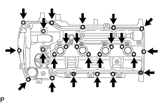
  1. A336469
    Remove the 21 bolts, 2 nuts, 2 plate washers, 2 seal washers and cylinder head cover sub-assembly.

  1. Remove the gasket from the cylinder head cover sub-assembly.

  1. Remove the No. 1 camshaft bearing cap oil hole gasket from the cylinder head cover spacer.


26. REMOVE CRANKSHAFT PULLEY

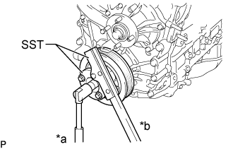
  1. A101288E04
    Using SST, hold the crankshaft pulley and loosen the crankshaft pulley set bolt.
    SST
    09213-54015   (91651-60855)
    09330-00021  
    Text in Illustration 
    *a
    Loosen
    *b
    Hold

  1. Screw the crankshaft pulley set bolt into the crankshaft by 2 or 3 threads.

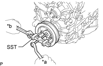
  1. A101289E05
    Using the crankshaft pulley set bolt and SST, remove the crankshaft pulley.
    SST
    09213-54015   (91651-60855)
    09330-00021  
    09950-50013   (09951-05010, 09952-05010, 09953-05010, 09954-05021)
    Text in Illustration 
    *a
    Loosen
    *b
    Hold

    HINT:
    Apply lubricant to the threads and end of SST.


27. REMOVE NO. 2 OIL PAN SUB-ASSEMBLY
  1. Remove the oil pan drain plug and gasket.

  1. A101291
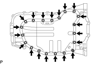
    Remove the 18 bolts and 2 nuts.

  1. Insert the blade of an oil pan seal cutter between the oil pan sub-assembly and No. 2 oil pan sub-assembly. Cut through the applied sealer and remove the No. 2 oil pan sub-assembly.

    NOTICE:
    Be careful not to damage the contact surfaces of the oil pan sub-assembly and No. 2 oil pan sub-assembly.


28. REMOVE OIL PAN SUB-ASSEMBLY

  1. A336471
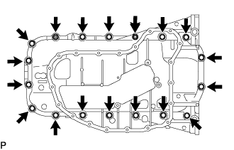
    Remove the 16 bolts and 2 nuts.

  1. A336472E03
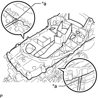
    Using a screwdriver wrapped in protective tape, remove the oil pan sub-assembly by prying between the oil pan sub-assembly and cylinder block sub-assembly as shown in the illustration.
    Text in Illustration 
    *a
    Protective Tape

    NOTICE:
    Be careful not to damage the contact surfaces of the cylinder block sub-assembly and oil pan sub-assembly.

    HINT:
    Tape the screwdriver tip before use.

  1. Remove the gasket.


29. REMOVE WATER INLET

  1. A087301
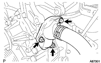
    Remove the 2 nuts and bolt and disconnect the water inlet.

  1. Remove the gasket.


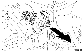
30. REMOVE THERMOSTAT

  1. A086841J01
    Remove the thermostat and gasket.


31. REMOVE TIMING CHAIN OR BELT COVER SUB-ASSEMBLY

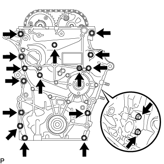
  1. A336797
    Remove the 16 bolts and nut shown in the illustration.

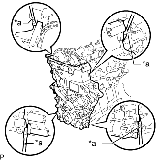
  1. A336764E01
    Using a screwdriver wrapped in protective tape, remove the timing chain or belt cover sub-assembly by prying the points in the illustration.
    Text in Illustration 
    *a
    Protective Tape

    NOTICE:
    Do not damage the surrounding parts.

    HINT:
    Tape the screwdriver tip before use.

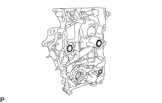
  1. A336765
    Remove the 3 O-rings from the timing chain or belt cover sub-assembly.


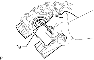
32. REMOVE TIMING CHAIN CASE OIL SEAL

  1. A336767E01
    Using a screwdriver wrapped in protective tape, pry out the timing chain case oil seal from the timing chain or belt cover sub-assembly.
    Text in Illustration 
    *a
    Protective Tape

    NOTICE:
    Be careful not to damage the timing chain or belt cover sub-assembly.

    HINT:
    Tape the screwdriver tip before use.


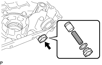
33. REMOVE OIL PUMP RELIEF VALVE

  1. A336768
    Using a 27 mm socket wrench, remove the oil pump relief valve plug and gasket.

  1. Remove the oil pump relief valve spring and oil pump relief valve from the timing chain or belt cover sub-assembly.

← REMOVAL (Jan 2015 – Mar 2016)REMOVAL (from Jan 2017) →