P1550 Battery Current Sensor Circuit
Diagnostic trouble codes · Vehicles built Apr 2016 – Dec 2016
Also covers:
- P1551 Battery Current Sensor Circuit Low
- P1552 Battery Current Sensor Circuit High
Versions by build date: Jan 2015 – Nov 2015 Dec 2015 – Mar 2016 Apr 2016 – Dec 2016 from Jan 2017
DESCRIPTION
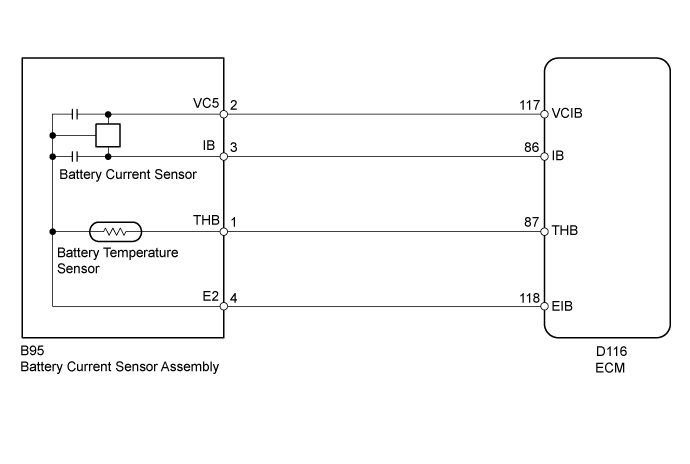
The battery current sensor assembly detects the battery charge and discharge current amount. The battery current sensor assembly changes this information into a voltage signal and outputs it to the ECM. Based on this signal, the ECM sends power generation voltage commands to the generator.| DTC Code |
DTC Detection Condition |
Trouble Area |
| P1550 |
When the ignition switch is ON, the difference between the maximum and minimum current values is less than 1 A for 10 seconds or more (1 trip detection logic). |
|
| P1551 |
When the ignition switch is ON, the battery current sensor output is less than 0.2 V for 0.5 seconds or more (1 trip detection logic). |
|
| P1552 |
When the ignition switch is ON, the battery current sensor output is higher than 4.8 V for 0.5 seconds or more (1 trip detection logic). |
|
MONITOR STRATEGY
| Frequency of operation |
Continuous |
CONFIRMATION DRIVING PATTERN
- Connect the GTS to the DLC3.
- Turn the ignition switch to ON and turn the GTS on.
- Clear the DTCs (even if no DTCs are stored, perform the clear DTC operation).
- Turn the ignition switch off and wait for at least 30 seconds.
- Turn the ignition switch to ON and turn the GTS on.
- Wait for 10 seconds or more.
- Enter the following menus: Powertrain / Engine and ECT / Trouble Code.
- Read Pending DTCs.
- HINT:
- If a pending DTC is output, the system is malfunctioning.
- If a pending DTC is not output, perform the following procedure.
- If a pending DTC is output, the system is malfunctioning.
- Enter the following menus: Powertrain / Engine and ECT / Utility / All Readiness.
- Input the DTC: P1550, P1551 or P1552.
- Check the DTC judgment result.
GTS Display
Description
NORMAL
- DTC judgment completed
- System normal
ABNORMAL
- DTC judgment completed
- System abnormal
INCOMPLETE
- DTC judgment not completed
- Perform driving pattern after confirming DTC enabling conditions
N/A
- Unable to perform DTC judgment
- Number of DTCs which do not fulfill DTC preconditions has reached ECU memory limit
- HINT:
- If the judgment result shows NORMAL, the system is normal.
- If the judgment result shows ABNORMAL, the system has a malfunction.
- If the judgment result shows INCOMPLETE or N/A, perform the Confirmation Driving Pattern and check the DTC judgment result again.
- If the judgment result shows NORMAL, the system is normal.
- DTC judgment completed
WIRING DIAGRAM

INSPECTION PROCEDURE
| 1. CHECK FOR DTC |

Connect the GTS to the DLC3.
Turn the ignition switch to ON.
Turn the GTS on.
According to the display on the GTS, check for DTCs (Click here).
- Result:
Result
Proceed to
DTC P1550, P1551 or P1552 is output.
A
DTCs other than P1550, P1551 and P1552 are output.
B
|
|
||||

| A | |
 |
| 2. READ VALUE USING GTS (BATTERY CURRENT) |
Connect the GTS to the DLC3.
Turn the ignition switch to ON and turn off all electrical devices (headlights, blower motor, wiper, rear defogger, etc.).
Turn the GTS on.
Select the item below in the Data List, and read the display on the GTS (Click here).
- Result:
Result
Proceed to
Current value displayed on GTS is fixed at 0 A and does not change, or only changes by 1 A or less between -98 and 98 A.
A
Current value displayed on GTS changes between -20 and 0 A.
B
|
|
||||
| A | |
|
| 3. INSPECT BATTERY CURRENT SENSOR ASSEMBLY |
Inspect the battery current sensor assembly (Click here).
|
|
||||
| OK | |
|
| 4. CHECK HARNESS AND CONNECTOR (ECM - BATTERY CURRENT SENSOR) |
Disconnect the ECM connector.
Disconnect the battery current sensor connector.
Measure the resistance according to the value(s) in the table below.
- Standard Resistance:
Tester Connection
Condition
Specified Condition
D116-117 (VCIB) - B95-2 (VC5)
Always
Below 1 Ω
D116-118 (EIB) - B95-4 (E2)
Always
Below 1 Ω
D116-86 (IB) - B95-3 (IB)
Always
Below 1 Ω
D116-117 (VCIB) or B95-2 (VC5) - Body ground
Always
10 kΩ or higher
D116-86 (IB) or B95-3 (IB) - Body ground
Always
10 kΩ or higher
|
|
||||
| OK | ||
 |
||
| ||