TERMINALS OF ECU
System information · Vehicles built from Dec 2015
Versions by build date: Oct 2014 – Nov 2015 from Dec 2015
| CHECK SLIDE DOOR CLOSER RELAY LH (w/o Power Slide Door) |
Disconnect the slide door closer relay LH connector.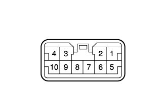

Measure the voltage and resistance according to the value(s) in the table below.
Terminal No. (Symbol)
Wiring Color
Terminal Description
Condition
Specified Condition
7 (GND) - Body ground
B - Body ground
Ground
Slide door LH fully open → fully close
Below 1 Ω
5 (+B) - Body ground
R - Body ground
Battery power supply
Slide door LH fully open → fully close
Below 1 V → 11 to 14 V
3 (HALF) - 8 (SWE)
Y - L
Latch switch condition
Slide door LH open → halfway position
Below 1 Ω → 10 kΩ or higher
4 (FULL) - 8 (SWE)
B - L
Latch switch condition
Slide door LH open → fully close
Below 1 Ω → 10 kΩ or higher
9 (PAWL) - 8 (SWE)
R - L
Pawl switch condition
Slide door LH fully close → open
10 kΩ or higher → Below 1 Ω
9 (PAWL) - 8 (SWE)
R - L
Pawl switch condition
Slide door LH halfway position
10 kΩ or higher
9 (PAWL) - 8 (SWE)
R - L
Pawl switch condition
Slide door LH open → fully close
10 kΩ or higher → Below 1 Ω
Reconnect the slide door closer relay LH connector.
Measure the voltage according to the value(s) in the table below.
Terminal No. (Symbol)
Wiring Color
Terminal Description
Condition
Specified Condition
1 (DC-) - 7 (GND)
B - B
Slide door LH motor normal rotation output
Slide door LH open → halfway position → normal rotation operation → revers rotation operation → operation stop
Below 1 V → Below 1 V → Below 1 V → 11 to 14 V → Below 1 V
2 (DC+) - 7 (GND)
R - B
Slide door LH motor revers rotation output
Slide door LH open → halfway position → normal rotation operation → revers rotation operation → operation stop
Below 1 V → Below 1 V → 11 to 14 V → Below 1 V → Below 1 V
10 (POS) - 8 (SWE)
G - L
Pawl switch condition
Slide door LH open → halfway position → normal rotation operation → pull the slide door outside handle or inside handle → revers rotation operation → operation stop
11 to 14 V → 11 to 14 V → 11 to 14 V → Below 1 V → 11 to 14 V
| CHECK SLIDE DOOR CLOSER RELAY RH (w/o Power Slide Door) |
Disconnect the slide door closer relay RH connector.
Measure the voltage and resistance according to the value(s) in the table below.
Terminal No. (Symbol)
Wiring Color
Terminal Description
Condition
Specified Condition
7 (GND) - Body ground
B - Body ground
Ground
Slide door RH fully open → fully close
Below 1 Ω
5 (+B) - Body ground
R - Body ground
Battery power supply
Slide door RH fully open → fully close
Below 1 V → 11 to 14 V
3 (HALF) - 8 (SWE)
Y - L
Latch switch condition
Slide door RH open → halfway position
Below 1 Ω → 10 kΩ or higher
4 (FULL) - 8 (SWE)
B - L
Latch switch condition
Slide door RH open → fully close
Below 1 Ω → 10 kΩ or higher
9 (PAWL) - 8 (SWE)
R - L
Pawl switch condition
Slide door RH fully close → open
10 kΩ or higher → Below 1 Ω
9 (PAWL) - 8 (SWE)
R - L
Pawl switch condition
Slide door RH halfway position
10 kΩ or higher
9 (PAWL) - 8 (SWE)
R - L
Pawl switch condition
Slide door RH open → fully close
10 kΩ or higher → Below 1 Ω
Reconnect the slide door closer relay RH connector.
Measure the voltage according to the value(s) in the table below.
Terminal No. (Symbol)
Wiring Color
Terminal Description
Condition
Specified Condition
1 (DC-) - 7 (GND)
B - B
Slide door RH motor normal rotation output
Slide door RH open → halfway position → normal rotation operation → revers rotation operation → operation stop
Below 1 V → Below 1 V → Below 1 V → 11 to 14 V → Below 1 V
2 (DC+) - 7 (GND)
R - B
Slide door RH motor revers rotation output
Slide door RH open → halfway position → normal rotation operation → revers rotation operation → operation stop
Below 1 V → Below 1 V → 11 to 14 V → Below 1 V → Below 1 V
10 (POS) - 8 (SWE)
G - L
Pawl switch condition
Slide door RH open → halfway position → normal rotation operation → pull the slide door outside handle or inside handle → revers rotation operation → operation stop
11 to 14 V → 11 to 14 V → 11 to 14 V → Below 1 V → 11 to 14 V
| CHECK DOOR CONTROL RELAY LH (w/o Power Slide Door) |
Disconnect the y2 door control relay LH connector.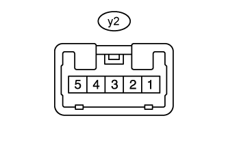
Measure the resistance and voltage according to the value(s) in the table below.
Terminal No. (Symbol)
Wiring Color
Terminal Description
Condition
Specified Condition
y2-1 (B) - Body ground
B-R - Body ground
Battery power supply
Always
11 to 14 V
y2-3 (E) - Body ground
W-B - Body ground
Ground
Always
Below 1 Ω
Reconnect the y2 door control rely LH connector.
Measure the voltage according to the value(s) in the table below.
Terminal No. (Symbol)
Wiring Color
Terminal Description
Condition
Specified Condition
y2-4 (SW) - Body ground
L - Body ground*1, *4
SB - Body ground*2, *3, *5
Battery power supply
Slide door LH open → halfway position
Below 1 V → 11 to 14 V
y2-5 (RLY) - Body ground
G - Body ground
Battery power supply
Slide door LH open → halfway position (slide door closer operate) → approximately 18 seconds after the slide door LH halfway position or slide door LH open
Below 1 V → 11 to 14 V → Below 1 V
- *1: for 2TR-FE w/o Step Light
- *2: for 1TR-FE
- *3: for 2TR-FE w/ Step Light
- *4: for 1KD-FTV w/o Entry and Start System
- *5: for 1KD-FTV w/ Entry and Start System
- *1: for 2TR-FE w/o Step Light
| CHECK DOOR CONTROL RELAY RH (w/o Power Slide Door) |
Disconnect the M2 door control relay RH connector.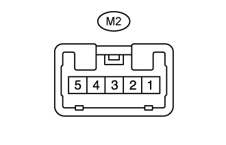
Measure the resistance and voltage according to the value(s) in the table below.
Terminal No. (Symbol)
Wiring Color
Terminal Description
Condition
Specified Condition
M2-1 (ECUB) - Body ground
B-R - Body ground
Battery power supply
Always
11 to 14 V
M2-3 (GND) - Body ground
W-B - Body ground
Ground
Always
Below 1 Ω
Reconnect the M2 door control rely RH connector.
Measure the voltage according to the value(s) in the table below.
Terminal No. (Symbol)
Wiring Color
Terminal Description
Condition
Specified Condition
M2-4 (FUL) - Body ground
B - Body ground
Battery power supply
Slide door RH open → halfway position
Below 1 V → 11 to 14 V
M2-5 (IG) - Body ground
G - Body ground
Battery power supply
Slide door RH open → halfway position (slide door closer operate) → approximately 18 seconds after the slide door RH halfway position or slide door RH open
Below 1 V → 11 to 14 V → Below 1 V
| CHECK DOOR CONTROL RELAY ASSEMBLY (for LH Side [w/ Power Slide Door]) |
Disconnect the q3 and q4 door control relay assembly connectors.
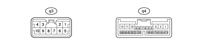
Measure the resistance and voltage according to the value(s) in the table below.
Terminal No. (Symbol)
Wiring Color
Terminal Description
Condition
Specified Condition
q3-7 (GND) - Body ground
W-B - Body ground
Ground
Always
Below 1 Ω
q3-8 (B) - Body ground
B-R - Body ground
Battery power supply
Always
11 to 14 V
q4-9 (IG) - Body ground
SB - Body ground
Ignition power supply
Ignition switch ON
11 to 14 V
q4-9 (IG) - Body ground
SB - Body ground
Ignition power supply
Ignition switch off
Below 1 V
q4-11 (ECUB) - Body ground
W - Body ground
Battery power supply
Always
11 to 14 V
q4-21 (SEL) - Body ground
W-B - Body ground
Ground
Always
Below 1 Ω
q4-5 (FUL) - Body ground
BE - Body ground
Full latch switch input
Slide door LH open → fully closed
Below 1 Ω → 10 kΩ or higher
q4-4 (HAF) - Body ground
B - Body ground
Half latch switch input
Slide door LH fully open → half latched
Below 1 Ω → 10 kΩ or higher
q4-18 (POL) - Body ground
R - Body ground
Pawl switch input
Slide door LH fully closed → half latched (latch pushed slightly toward full latch position)
10 kΩ or higher → Below 1 Ω → 10 kΩ or higher
q4-18 (POL) - Body ground
R - Body ground
Pawl switch input
Half latched
Below 1 Ω
q4-18 (POL) - Body ground
R - Body ground
Pawl switch input
Slide door LH fully open → half latched (latch pushed slightly toward full latch position)
10 kΩ or higher → Below 1 Ω → 10 kΩ or higher
Reconnect the q3 and q4 door control relay assembly connectors.
Measure the voltage according to the value(s) in the table below.
Terminal No. (Symbol)
Wiring Color
Terminal Description
Condition
Specified Condition
Q3-1 (DC-) - Body ground
P - Body ground
Door closer output
Slide door LH open → halfway position → normal rotation operation → revers rotation operation → operation stop
Below 1 V → Below 1 V → Below 1 V → 11 to 14 V → Below 1 V
Q3-5 (DC+) - Body ground
L - Body ground
Door closer output
Slide door LH open → halfway position → normal rotation operation → revers rotation operation → operation stop
Below 1 V → Below 1 V → 11 to 14 V → Below 1 V → Below 1 V
Q4-19 (LMT) - Body ground
W - Body ground
Initial position switch input
Slide door LH open → halfway position → normal rotation operation → pull the slide door outside handle or inside handle → revers rotation operation → operation stop
11 to 14 V → 11 to 14 V → Below 1 V → 11 to 14 V → Below 1 V → 11 to 14 V
| CHECK DOOR CONTROL RELAY ASSEMBLY (for RH Side [w/ Power Slide Door]) |
Disconnect the I3 and I4 door control relay assembly connectors.
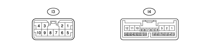
Measure the resistance and voltage according to the value(s) in the table below.
Terminal No. (Symbol)
Wiring Color
Terminal Description
Condition
Specified Condition
I3-7 (GND) - Body ground
W-B - Body ground
Ground
Always
Below 1 Ω
I3-8 (B) - Body ground
B-R - Body ground
Battery power supply
Always
11 to 14 V
I4-9 (PCV1) - Body ground
B - Body ground
Ignition power supply
Ignition switch ON
11 to 14 V
I4-9 (PCV1) - Body ground
B - Body ground
Ignition power supply
Ignition switch off
Below 1 V
I4-11 (ECUB) - Body ground
W - Body ground
Battery power supply
Always
11 to 14 V
I4-21 (SEL) - Body ground
W-B - Body ground
Ground
Always
Below 1 Ω
I4-5 (FUL) - Body ground
Y - Body ground
Full latch switch input
Slide door RH open → fully closed
Below 1 Ω → 10 kΩ or higher
I4-4 (HAF) - Body ground
B - Body ground
Half latch switch input
Slide door RH fully open → half latched
Below 1 Ω → 10 kΩ or higher
I4-18 (POL) - Body ground
R - Body ground
Pawl switch input
Slide door RH fully closed → half latched (latch pushed slightly toward full latch position)
10 kΩ or higher → Below 1 Ω → 10 kΩ or higher
I4-18 (POL) - Body ground
R - Body ground
Pawl switch input
Half latched
Below 1 Ω
I4-18 (POL) - Body ground
R - Body ground
Pawl switch input
Slide door RH fully open → half latched (latch pushed slightly toward full latch position)
10 kΩ or higher → Below 1 Ω → 10 kΩ or higher
Reconnect the I3 and I4 door control relay assembly connectors.
Measure the voltage according to the value(s) in the table below.
Terminal No. (Symbol)
Wiring Color
Terminal Description
Condition
Specified Condition
I3-1 (DC-) - Body ground
P - Body ground
Door closer output
Slide door RH open → halfway position → normal rotation operation → revers rotation operation → operation stop
Below 1 V → Below 1 V → Below 1 V → 11 to 14 V → Below 1 V
I3-5 (DC+) - Body ground
L - Body ground
Door closer output
Slide door RH open → halfway position → normal rotation operation → revers rotation operation → operation stop
Below 1 V → Below 1 V → 11 to 14 V → Below 1 V → Below 1 V
I4-19 (LMT) - Body ground
W - Body ground
Initial position switch input
Slide door RH open → halfway position → normal rotation operation → pull the slide door outside handle or inside handle → revers rotation operation → operation stop
11 to 14 V → 11 to 14 V → Below 1 V → 11 to 14 V → Below 1 V → 11 to 14 V