INSTALLATION
Removal / installation · Vehicles built Jan 2015 – Mar 2016
Versions by build date: Oct 2014 – Dec 2014 Jan 2015 – Mar 2016 Apr 2016 – Dec 2016 from Jan 2017
- HINT:
- w/ Dual VVT-i:
- Perform "Inspection After Repairs" after replacing the engine coolant temperature sensor (Click here).
| 1. INSTALL ENGINE COOLANT TEMPERATURE SENSOR |

- HINT:
- w/ Dual VVT-i:
- Perform "Inspection After Repairs" after replacing the engine coolant temperature sensor (Click here).
Install a new gasket onto the engine coolant temperature sensor.
Using a 19 mm deep socket wrench, install the engine coolant temperature sensor.
- Torque:
- 20 N*m{ 200 kgf*cm , 14 ft.*lbf }
Connect the engine coolant temperature sensor connector.
| 2. INSTALL INTAKE MANIFOLD |
Install a new gasket onto the intake manifold.
w/ Dual VVT-i: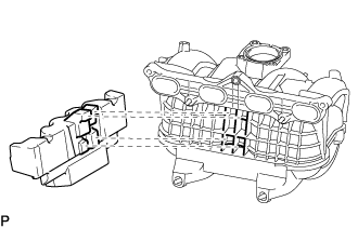

Install the intake manifold insulator to the intake manifold.
- HINT:
- Insert the protrusions of the intake manifold insulator into the grille of the intake manifold.
- NOTICE:
-
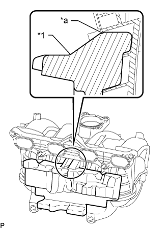
- Insert the intake manifold insulator until the position of the line as shown in the illustration.
Text in Illustration *1
Intake Manifold Insulator
*a
Line
Install the intake manifold with the 5 bolts and 2 nuts.
- Torque:
- 25 N*m{ 255 kgf*cm , 18 ft.*lbf }
Install the bolt and wire harness bracket to the intake manifold.
- Torque:
- 8.5 N*m{ 87 kgf*cm , 75 in.*lbf }
Connect the vacuum hose to the intake manifold, and slide the clamp to secure the hose.
Connect the No. 3 PCV hose to the intake manifold, and slide the clamp to secure the hose.
Attach the 2 wire harness clamps to the wire harness bracket.
Connect the purge line hose to the vacuum switching valve, and slide the clamp to secure the hose.
Connect the vacuum switching valve connector.
| 3. INSTALL TRANSMISSION OIL FILLER TUBE SUB-ASSEMBLY (for Automatic Transmission) |
- for A343E: (Click here)
| 4. INSTALL FUEL INJECTOR ASSEMBLY |
| 5. INSTALL THROTTLE BODY ASSEMBLY |
| 6. CONNECT CABLE TO NEGATIVE BATTERY TERMINAL |
- NOTICE:
- When disconnecting the cable, some systems need to be initialized after the cable is reconnected (Click here).
| 7. CHECK FOR FUEL LEAKS |
| 8. CHECK FOR ENGINE COOLANT LEAKS |
| 9. INSPECT FUNCTION OF THROTTLE BODY |
| 10. SYSTEM INITIALIZE |