REASSEMBLY
Removal / installation · Vehicles built from Oct 2014
| 1. INSTALL PLANETARY GEAR |

Apply high-temperature grease to the planetary gears, pin parts of the planetary shaft and inside of plate.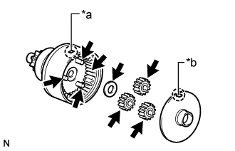

Text in Illustration *a
Protrusion
*b
Cutout

High-temperature Grease
Install the plate washer and 3 planetary gears.
Align the cutout of the plate with the protrusion inside the starter center bearing clutch sub-assembly, and install the plate.
| 2. INSTALL STARTER CENTER BEARING CLUTCH SUB-ASSEMBLY |
Apply high-temperature grease to the starter drive lever.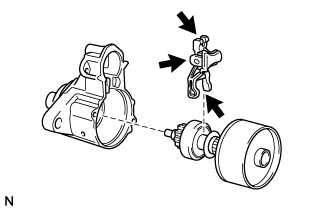
Text in Illustration
High-temperature Grease
Install the starter drive lever to the starter center bearing clutch sub-assembly.
Align the protrusion of the starter center bearing clutch sub-assembly with the cutout of the starter drive housing assembly and install the starter drive lever and starter center bearing clutch sub-assembly.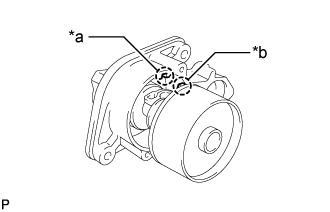
Text in Illustration *a
Cutout
*b
Protrusion
| 3. INSTALL STARTER ARMATURE ASSEMBLY |
Install the starter armature assembly to the starter yoke assembly.
| 4. INSTALL STARTER BRUSH HOLDER ASSEMBLY |
Install 2 new O-rings to the starter yoke assembly.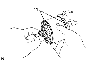
Text in Illustration *1
O-Ring
Install the starter brush holder assembly to the starter armature assembly.
Install the 4 starter brushes to the starter brush holder assembly.
Using a screwdriver, pull back the spring.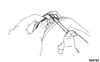
- NOTICE:
- Check that the positive (+) lead wires are not grounded.
Install the brush to the starter brush holder assembly.
| 5. INSTALL STARTER COMMUTATOR END FRAME ASSEMBLY |
Apply spindle oil to the bearing of the starter commutator end frame assembly.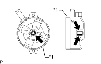
Text in Illustration *1
Starter Commutator End Frame Assembly
Spindle Oil
Install the starter commutator end frame assembly with the 2 screws.
- Torque:
- 1.5 N*m{ 15 kgf*cm , 13 in.*lbf }
| 6. INSTALL STARTER YOKE ASSEMBLY |
Align the cutout of the starter yoke assembly with the protrusion of the starter center bearing clutch sub-assembly.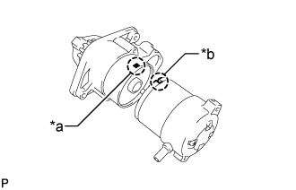
Text in Illustration *a
Protrusion
*b
Cutout
Install the starter yoke assembly together with the starter armature assembly with the 2 through bolts.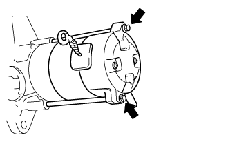
- Torque:
- 5.9 N*m{ 60 kgf*cm , 52 in.*lbf }
| 7. INSTALL MAGNET STARTER SWITCH ASSEMBLY |
Install the plunger cover to the magnet starter switch assembly.
Attach the plunger of the magnet starter switch assembly to the starter drive lever from the upper side.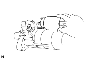
Install the magnet starter switch assembly with the 2 nuts.
- Torque:
- 8.3 N*m{ 85 kgf*cm , 73 in.*lbf }
Connect the lead wire to terminal C with the nut.
- Torque:
- 9.8 N*m{ 100 kgf*cm , 87 in.*lbf }