CLUTCH CLUTCH UNIT REMOVAL
CAUTION / NOTICE / HINT
The necessary procedures (adjustment, calibration, initialization, or registration) that must be performed after parts are removed and installed, or replaced during clutch unit removal/installation are shown below.
| Replaced Part or Performed Procedure | Necessary Procedure | Effect/Inoperative Function when Necessary Procedure not Performed | Link |
|---|---|---|---|
| Disconnect cable from negative(-) battery terminal | Memorize steering angle neutral point | Parking assist monitor system | ( ) |
for 7GR-FKS:
·
Gas leaks from exhaust system |
Inspection after repair | ·
Poor idle, etc. ·
Engine start function, etc. |
()
|
w/ Stop and Start System:
Starter assembly
|
Clear the number of starter operations | Stop and start system | ()
|
- CAUTION:
- ·
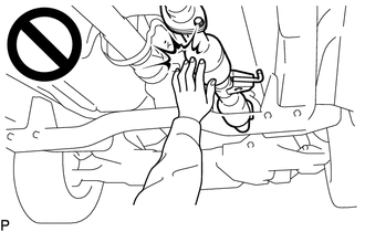
To prevent burns, do not touch the engine, exhaust pipe or other high temperature components while the engine is hot.
·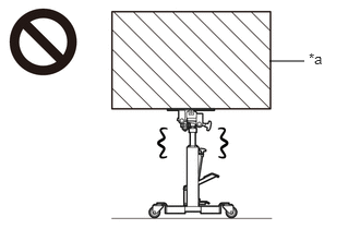 2.573,0.583 2.906,0.583 false 2.948,0.479 3.26,0.677 0.313,0.198 10 false *a
*a Object Exceeding Weight Limit of Transmission Jack
The manual transmission assembly is very heavy. Be sure to follow the procedure described in the repair manual, or the transmission jack may suddenly drop or a part may fall.
- HINT:
-
When the cable is disconnected / reconnected to the battery terminal, systems temporarily stop operating. However, each system has a function that completes learning the first time the systems is used.
- ·
Learning completes when vehicle is driven
Effect/Inoperative Function When Necessary Procedures are not Performed Necessary Procedures Link Stop and start system Drive the vehicle until stop and start control is permitted (approximately 5 to 60 minutes). ( )
Lane control system Drive the vehicle straight ahead at 15 km/h (10 mph) or more for 1 second or more. ( )
Pre-collision system
·Learning completes when vehicle is operated normally
Effect/Inoperative Function When Necessary Procedures are not Performed Necessary Procedures Link Power slide door system Fully close the slide door by hand.
- HINT:
-
Initialization is not necessary if the above procedures are performed while the slide door is closed.
( )
Air conditioning system After the ignition switch is turned to ON, the servo motor standard position is recognized. -
PROCEDURE

 1. PRECAUTION
- NOTICE:
-
After turning the ignition switch off, waiting time may be required before disconnecting the cable from the negative (-) battery terminal.
-
Click hereGeneral>SETUP>WHEN DISCONNECTING OR RECONNECTING BATTERY TERMINAL>BEFORE DISCONNECTING BATTERY
2.REMOVE MANUAL TRANSMISSION ASSEMBLY
31126
3.REMOVE CLUTCH RELEASE FORK BOOT (for 1GD-FTV)
Remove the clutch release fork boot from the manual transmission assembly.
31230
4.REMOVE CLUTCH RELEASE BEARING ASSEMBLY
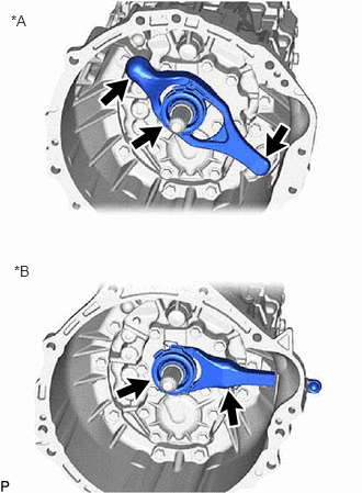
| *A | for 7GR-FKS |
| *B | for 1GD-FTV |
Remove the clutch release fork sub-assembly with the clutch release bearing assembly from the manual transmission assembly.
Remove the clutch release fork sub-assembly from the clutch release bearing assembly.
- NOTICE:
-
If the clutch release fork collar comes off from the clutch release fork sub-assembly, replace the clutch release fork collar and clutch release fork dust seal with new ones.
31236B
5.REMOVE RELEASE FORK SUPPORT
Remove the release fork support from the manual transmission assembly.
31210
6.REMOVE CLUTCH COVER ASSEMBLY
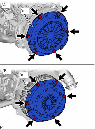
| *A | for 7GR-FKS |
| *B | for 1GD-FTV |
| *a | Matchmark |
Put matchmarks on the clutch cover assembly and flywheel sub-assembly.
Loosen each bolt one turn at a time in the order shown in the illustration until the spring tension is released.
Remove the set bolts and pull off the clutch cover assembly.
- NOTICE:
-
Do not drop the clutch disc assembly.
31250
7.REMOVE CLUTCH DISC ASSEMBLY
- NOTICE:
-
Keep the lining part of the clutch disc, the pressure plate and the surface of the flywheel away from oil and foreign matter.
31241
8.REMOVE CLUTCH RELEASE FORK DUST SEAL
Remove the clutch release fork collar from the clutch release fork sub-assembly.
Remove the clutch release fork dust seal from the clutch release fork sub-assembly.