RC60J MANUAL TRANSMISSION / TRANSAXLE MANUAL TRANSMISSION ASSEMBLY(for 1GD-FTV) REMOVAL
CAUTION / NOTICE / HINT
The necessary procedures (adjustment, calibration, initialization, or registration) that must be performed after parts are removed and installed, or replaced during manual transmission assembly removal/installation are shown below.
| Replaced Part or Performed Procedure | Necessary Procedure | Effect/Inoperative Function when Necessary Procedure not Performed | Link |
|---|---|---|---|
| Disconnect cable from negative(-) battery terminal | Memorize steering angle neutral point | Parking assist monitor system | ( ) |
w/ Stop and Start System:
Starter assembly
|
Clear the number of starter operations | Stop and start system | ()
|
- CAUTION:
- ·
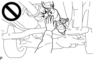
To prevent burns, do not touch the engine, exhaust pipe or other high temperature components while the engine is hot.
·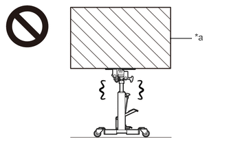 2.573,0.583 2.906,0.583 false 2.948,0.479 3.26,0.677 0.313,0.198 10 false *a
*a Object Exceeding Weight Limit of Transmission Jack
The manual transmission assembly is very heavy. Be sure to follow the procedure described in the repair manual, or the transmission jack may suddenly drop or a part may fall.
- HINT:
-
When the cable is disconnected / reconnected to the battery terminal, systems temporarily stop operating. However, each system has a function that completes learning the first time the systems is used.
- ·
Learning completes when vehicle is driven
Effect/Inoperative Function When Necessary Procedures are not Performed Necessary Procedures Link Stop and start system Drive the vehicle until stop and start control is permitted (approximately 5 to 60 minutes). ( )
Lane control system Drive the vehicle straight ahead at 15 km/h (10 mph) or more for 1 second or more. ( )
Pre-collision system
·Learning completes when vehicle is operated normally
Effect/Inoperative Function When Necessary Procedures are not Performed Necessary Procedures Link Power slide door system Fully close the slide door by hand.
- HINT:
-
Initialization is not necessary if the above procedures are performed while the slide door is closed.
( )
Air conditioning system After the ignition switch is turned to ON, the servo motor standard position is recognized. -
PROCEDURE

 1. PRECAUTION
- NOTICE:
-
After turning the ignition switch is turned off, there may be a waiting time before disconnecting the negative (-) battery terminal.
-
Click hereGeneral>SETUP>WHEN DISCONNECTING OR RECONNECTING BATTERY TERMINAL>BEFORE DISCONNECTING BATTERY
28800
2.DISCONNECT CABLE FROM NEGATIVE BATTERY TERMINAL
17410
3.REMOVE FRONT EXHAUST PIPE ASSEMBLY
37100
4.REMOVE PROPELLER SHAFT WITH CENTER BEARING ASSEMBLY
for Standard Roof:
Click hereDrivetrain>DRIVE SHAFT / PROPELLER SHAFT>PROPELLER SHAFT ASSEMBLY (for Standard Roof)>REMOVAL
for High Roof:
Click hereDrivetrain>DRIVE SHAFT / PROPELLER SHAFT>PROPELLER SHAFT ASSEMBLY (for High Roof)>REMOVAL
28100
5.REMOVE STARTER ASSEMBLY
for 2.0 kW Type:
Click hereEngine / Hybrid System>1GD-FTV (STARTING)>STARTER (for 2.0 kW Type)>REMOVAL
for 3.0 kW Type:
Click hereEngine / Hybrid System>1GD-FTV (STARTING)>STARTER (for 3.0 kW Type)>REMOVAL
w/ Stop and Start System:
Click hereEngine / Hybrid System>1GD-FTV (STARTING)>STARTER (w/ Stop And Start System)>REMOVAL
6.DRAIN MANUAL TRANSMISSION OIL
31470
7.DISCONNECT CLUTCH RELEASE CYLINDER ASSEMBLY
- HINT:
-
Leave the clutch release cylinder assembly remaining on the vehicle side, as the clutch release cylinder to flexible hose tube is not disconnected during the procedure.
33119
8.REMOVE STIFFENER PLATE LH(MTM)
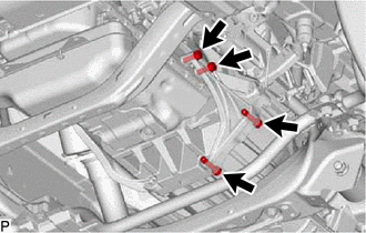
Remove the 4 bolts and stiffener plate LH(MTM) from the engine assembly and manual transmission assembly.
33118
9.REMOVE STIFFENER PLATE RH(MTM)
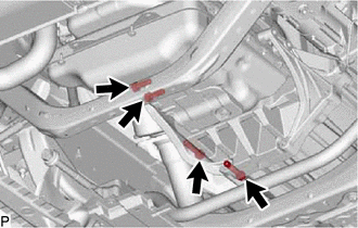
Remove the 4 bolts and stiffener plate RH(MTM) from the engine assembly and manual transmission assembly.
12584
10.REMOVE NO. 4 CYLINDER BLOCK INSULATOR
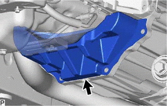
Remove the No. 4 cylinder block insulator from the engine assembly and manual transmission assembly.
11.REMOVE NO. 2 REAR END PLATE
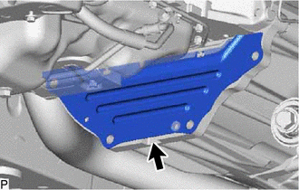
Remove the No. 2 rear end plate from the engine assembly and manual transmission assembly.
31121
12.REMOVE NO. 1 CLUTCH HOUSING COVER
- HINT:
-
There is no need to remove this unless the No. 1 clutch housing cover is replaced.
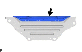
Remove the No. 1 clutch housing cover from the No. 2 rear end plate.
33820B
13.DISCONNECT TRANSMISSION CONTROL CABLE ASSEMBLY (for Transmission Assembly Side)
51446B
14.REMOVE NO. 2 ENGINE UNDER COVER BRACKET
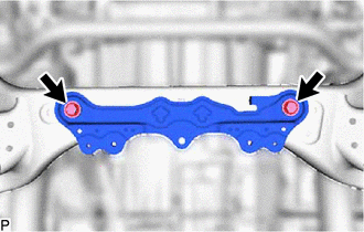
Remove the 2 bolts and No. 2 engine under cover bracket from the frame.
15.SUPPORT MANUAL TRANSMISSION ASSEMBLY
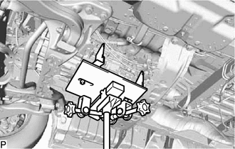
Support the manual transmission assembly with a transmission jack.
- NOTICE:
- ·
Make sure the high transmission jack attachment is centered on the safety stand.
·Secure the part with a rope, attachment, etc.
57209B
16.REMOVE REAR ENGINE MOUNTING MEMBER SUB-ASSEMBLY
w/ Cover:
Remove the step plate cover RH.
Click hereEngine / Hybrid System>1GD-FTV (ENGINE MECHANICAL)>ENGINE ASSEMBLY>REMOVAL
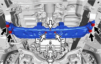

|
Bolt |

|
Nut |
Remove the 3 nuts from the rear engine mounting member sub-assembly.
Remove the 4 bolts and rear engine mounting member sub-assembly from the body.
12380
17.REMOVE REAR ENGINE MOUNTING INSULATOR ASSEMBLY
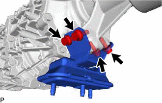
Remove the 4 bolts and rear engine mounting insulator assembly from the manual transmission assembly.
18.DISCONNECT WIRE HARNESS
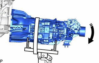

|
Tilt Down |
Tilt down the manual transmission assembly.
- NOTICE:
-
Make sure that the cooling fan and fan shroud do not contact the engine assembly when tilting the manual transmission assembly.
Detach the 6 wire harness clamps.
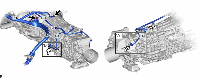
| *A | w/ Stop and Start System | *B | w/ Sensor |
|
|
Bolt |
|
Transmission Revolution Sensor Connector |

|
Back-up Light Switch Assembly Connector | 
|
Neutral Position Switch Connector |
Disconnect the back-up light switch assembly connector.
w/ Stop and Start System:
Detach the wire harness clamp and disconnect the neutral position switch connector.
w/ Sensor:
Detach the wire harness clamp and disconnect the transmission revolution sensor connector.
Remove the 2 bolts and disconnect the wire harness.
19.REMOVE MANUAL TRANSMISSION ASSEMBLY
Using an engine lifter, jacks, etc., support the engine at an angle where the manual transmission assembly can be removed and in such a manner that the engine angle remains the same after the manual transmission assembly is removed.
- NOTICE:
-
Make sure that the engine does not contact parts such as the body panel or fan shroud.
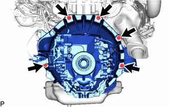
Remove the 5 bolts and manual transmission assembly.
- NOTICE:
-
As the manual transmission assembly is very heavy, be sure to support it securely.
33827
20.REMOVE NO. 3 TRANSMISSION CONTROL CABLE BRACKET
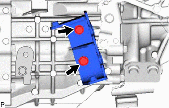
Remove the 2 bolts and No. 3 transmission control cable bracket from the manual transmission assembly.
21.REMOVE WIRING HARNESS CLAMP BRACKET
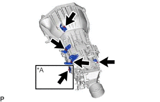
| *A | w/ Sensor |
w/ Sensor:
Remove the 5 bolts and 5 wiring harness clamp brackets from the manual transmission assembly.
w/o Sensor:
Remove the 4 bolts and 4 wiring harness clamp brackets from the manual transmission assembly.
33146
22.REMOVE EXTENSION HOUSING DUST(MTM) DEFLECTOR
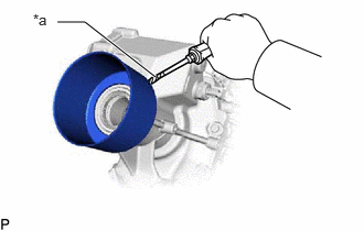
| *a | Protective Tape |
Using a screwdriver, pry out the extension housing dust(MTM) deflector.
- NOTICE:
-
Be careful not to damage the extension housing sub-assembly.
- HINT:
-
Tape the screwdriver tip before use.