RC60J MANUAL TRANSMISSION / TRANSAXLE MANUAL TRANSMISSION SYSTEM(for 7GR-FKS) P071531 Input/Turbine Speed Sensor "A" No Signal P08051C Clutch Position Sensor "A" Circuit Voltage Out of Range P081174 Excessive Clutch "A" Slippage Actuator Slipping
DESCRIPTION
| DTC No. | Detection Item | DTC Detection Condition | Trouble Area | MIL | Memory | Note |
|---|---|---|---|---|---|---|
| P071531 | Input/Turbine Speed Sensor "A" No Signal | While driving after warm-up with clutch engaged, transmission input speed is not input
(1-trip detection logic) |
·
Harness and connector ·
Transmission revolution sensor ·
ECM |
Does not come on | DTC stored | SAE Code:
P0717 |
| P08051C | Clutch Position Sensor "A" Circuit Voltage Out of Range | While driving after warm-up with clutch engaged, clutch pedal stroke sensor assembly value continuously indicates clutch disengaged
(1-trip detection logic) |
·
Harness and connector ·
Clutch pedal stroke sensor ·
ECM |
Does not come on | DTC stored | SAE Code:
P0806 |
| P081174 | Excessive Clutch "A" Slippage Actuator Slipping | With clutch completely engaged, divergence between transmission input speed and engine speed is continuously greater than threshold
(1-trip detection logic) |
·
Harness and connector ·
Transmission revolution sensor ·
Clutch pedal stroke sensor ·
Clutch slippage ·
ECM |
Does not come on | DTC stored | SAE Code:
P0811 |
CONFIRMATION DRIVING PATTERN
- HINT:
-
After repairs have been completed, clear the DTCs and then check that the vehicle has returned to normal by performing the following All Readiness check procedure.
Connect the GTS to the DLC3.
Turn the ignition switch to ON and turn the GTS on.
Clear the DTCs (even if no DTCs are stored, perform the clear DTC procedure).
Turn the ignition switch off and wait for 30 seconds or more.
Turn the ignition switch to ON and turn the GTS on.
Perform the Road Test.
Enter the following menus: Powertrain / Engine / Utility / All Readiness.
Input the DTC: P071531, P08051C or P081174.
Check the DTC judgment result.
| GTS Display | Description |
|---|---|
| NORMAL | ·
DTC judgment completed ·
System normal |
| ABNORMAL | ·
DTC judgment completed ·
System abnormal |
| INCOMPLETE | ·
DTC judgment not completed ·
Perform driving pattern after confirming DTC enabling conditions |
| N/A | ·
Unable to perform DTC judgment ·
Number of DTCs which do not fulfill DTC preconditions has reached ECU memory limit |
- HINT:
- ·
If the judgment result shows NORMAL, the system is normal.
·If the judgment result shows ABNORMAL, the system has a malfunction.
·If the judgment result shows INCOMPLETE or N/A, perform the Confirmation Driving Pattern and check the DTC judgment result again.
WIRING DIAGRAM
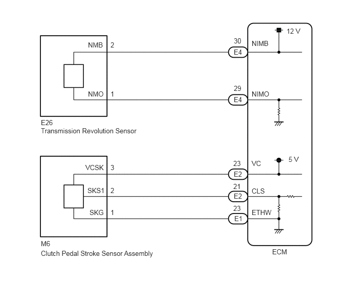
CAUTION / NOTICE / HINT
- NOTICE:
-
Perform registration and/or initialization when parts related to the iMT system are replaced.
PROCEDURE
Connect the GTS to the DLC3.
Turn the ignition switch to ON.
Turn the GTS on.
Enter the following menus: Powertrain / Transmission / Dual Data List.
Simultaneously display the "NIM Sensor Speed" transmission Data List item and the "Engine Speed" engine Data List item.
According to the display on the GTS, read the Data List.
| Tester Display | Measurement Item | Range | Normal Condition | Diagnostic Note |
|---|---|---|---|---|
| NIM Sensor Speed | Input shaft speed (NIM) | Min.: 0 rpm
Max.: 16383 rpm |
Input shaft speed (NIM) equal to engine speed (NE): Clutch pedal not depressed, vehicle running | - |
| Tester Display | Measurement Item | Range | Normal Condition | Diagnostic Note |
|---|---|---|---|---|
| Engine Speed | Engine speed | Min.: 0 rpm
Max.: 16383 rpm |
550 to 700 rpm: Idling (shift lever in neutral, engine warmed up and A/C off) | When the crankshaft position sensor is malfunctioning, "Engine Speed" is approximately 0 rpm or varies greatly from the actual engine speed. |
- OK:
When the clutch is engaged, the engine speed is constant and the difference between "NIM Sensor Speed" and "Engine Speed" in the Data List is below 200 rpm.
- Result:
Proceed to OK NG
OK
NG
Connect the GTS to the DLC3.
Turn the ignition switch to ON.
Turn the GTS on.
Enter the following menus: Powertrain / Transmission / Data List.
According to the display on the GTS, read the Data List.
- Powertrain > Transmission > Data List
-
Tester Display Measurement Item Range Normal Condition Diagnostic Note Clutch Stroke Position Clutch pedal stroke calculated by ECM Min.: -200%
Max.: 199.9%Value increases: Clutch pedal released → clutch pedal fully depressed -
- Powertrain > Transmission > Data List
-
Tester Display Clutch Stroke Position - 50003 373 606
- Result:
Result Proceed to Data display is within Normal Condition range A Data display is not within Normal Condition range B
A
B
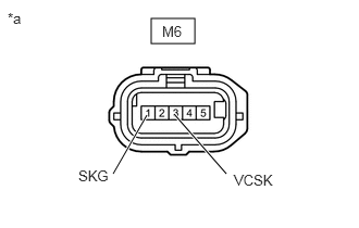
| *a | Front view of wire harness connector
(to Clutch Pedal Stroke Sensor Assembly) |
Disconnect the clutch pedal stroke sensor assembly connector.
Turn the ignition switch to ON.
Measure the voltage according to the value(s) in the table below.
- Standard Voltage:
Tester Connection Switch Condition Specified Condition M6-3 (VCSK) - M6-1 (SKG) Ignition switch ON 4.5 to 5.5 V
- Result:
Proceed to OK NG
OK
NG
Disconnect the ECM connector.
Disconnect the clutch pedal stroke sensor assembly connector.
Measure the resistance according to the value(s) in the table below.
- Standard Resistance:
Tester Connection Condition Specified Condition M6-2 (SKS1) - E2-21 (CLS) Always Below 1 Ω M6-2 (SKS1) or E2-21 (CLS) - Body ground Always 10 kΩ or higher
- Result:
Proceed to OK NG
OK
NG
Replace the clutch pedal stroke sensor assembly.
- Result:
Proceed to NEXT
NEXT
Connect the GTS to the DLC3.
Turn the ignition switch to ON.
Turn the GTS on.
Clear the DTCs.
- Powertrain > Transmission > Clear DTCs
- 50002 373
Turn the ignition switch off and wait for at least 30 seconds.
Perform the Road Test.
Enter the following menus: Powertrain / Transmission / Trouble Codes.
- Powertrain > Transmission > Trouble Codes
- 50001 373
Read the DTCs.
- Result:
Result Proceed to DTCs are not output A DTC P08051C or P081174 is output B
A
B
Disconnect the ECM connector.
Disconnect the clutch pedal stroke sensor assembly connector.
Measure the resistance according to the value(s) in the table below.
- Standard Resistance:
Tester Connection Condition Specified Condition M6-1 (SKG) - E1-23 (ETHW) Always Below 1 Ω M6-3 (VCSK) - E2-23 (VC) Always Below 1 Ω M6-1 (SKG) or E1-23 (ETHW) - Body ground Always 10 kΩ or higher M6-3 (VCSK) or E2-23 (VC) - Body ground Always 10 kΩ or higher
- Result:
Proceed to OK NG
OK
NG
Refer to the "Clutch slips" item in the problem symptoms table for the clutch system and check each part.
Click hereDrivetrain>CLUTCH>CLUTCH SYSTEM>PROBLEM SYMPTOMS TABLE
- OK:
Inspections of all suspected areas are normal.
- Result:
Proceed to OK NG
OK
NG
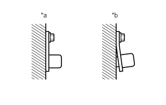
| *a | CORRECT |
| *b | INCORRECT |
Check the transmission revolution sensor installation.
- OK:
The installation bolt is tightened properly and there is no clearance between the sensor and transmission case.
- Result:
Proceed to OK NG
OK
NG
Disconnect the transmission revolution sensor connector.
Disconnect the ECM connector.
Measure the resistance according to the value(s) in the table below.
- Standard Resistance:
Tester Connection Condition Specified Condition E26-2 (NMB) - E4-30 (NIMB) Always Below 1 Ω E26-1 (NMO) - E4-29 (NIMO) Always Below 1 Ω E26-2 (NMB) or E4-30 (NIMB) - Body ground Always 10 kΩ or higher E26-1 (NMO) or E4-29 (NIMO) - Body ground Always 10 kΩ or higher
- Result:
Proceed to OK NG
OK
NG
Inspect transmission revolution sensor.
Click hereDrivetrain>RC60J (MANUAL TRANSMISSION / TRANSAXLE)>SPEED SENSOR>INSPECTION
- Result:
Proceed to OK NG
OK
NG
Inspect the teeth of the countershaft 2nd speed gear.
- OK:
No tooth damage on countershaft 2nd speed gear.
- Result:
Proceed to OK NG
OK
NG