RC60J MANUAL TRANSMISSION / TRANSAXLE SHIFT AND SELECT TRANSMISSION CONTROL CABLE INSTALLATION
CAUTION / NOTICE / HINT
- NOTICE:
-
The stopper spring used to prevent improper installation that is included with the shift lever supply part is removed in the transmission control cable assembly adjustment procedure.
PROCEDURE

 33820B
1.INSTALL TRANSMISSION CONTROL CABLE ASSEMBLY
- NOTICE:
-
Do not bend the transmission control cable assembly within a radius of 120 mm (4.72 in.).
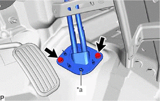
| *a | Retainer Arrow |
Install the transmission control cable assembly to the outside the vehicle body with the 2 bolts.
- Torque:
- 5.5 N*m (56 kgf*cm, 49 in.*lbf)
- NOTICE:
- ·
Make sure that the retainer arrow faces the front of the vehicle.
·Before installing the shift lever assembly, temporarily place the transmission control cable assembly behind the pedal arm.
When temporarily placing the transmission control cable assembly, check that it is not damaged.
If the transmission control cable assembly is damaged, replace it with a new one.
33820B
2.CONNECT TRANSMISSION CONTROL CABLE ASSEMBLY
- NOTICE:
-
Do not bend the transmission control cable assembly within a radius of 120 mm (4.72 in.).
for Shift Lever Assembly Side:
Turn the lock nut of the transmission control cable assembly 180° clockwise. While holding the lock nut in place, push in the cable lock to lock the lock nut.
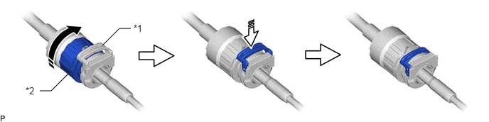
| *1 | Cable Lock | *2 | Lock Nut |

|
Rotate approximately 180° | 
|
Push In |
- NOTICE:
-
Do not over-rotate the nut as it will come off the internal spring and the transmission control cable assembly will not be reusable.
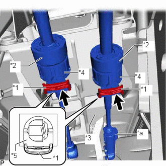
| *1 | Cable Lock |
| *2 | Lock Nut |
| *3 | Shift Lever Assembly |
| *4 | Socket |
| *5 | Case |
| *a | Adjustment Mechanism Lock Piece |
Connect the outer part of the transmission control cable assembly to the shift lever assembly. Check that the cable lock returns to the pulled-out position.
- NOTICE:
- ·
Align with the socket and insert.
·Make sure that it is installed with the adjustment mechanism lock piece facing the left side of the vehicle.
·After connecting the transmission control cable assembly, check that the cable lock protrudes from the case.
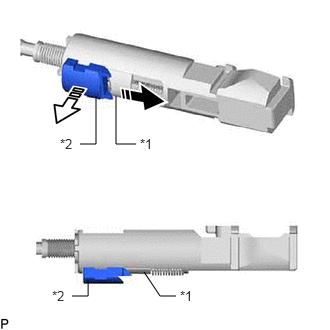
| *1 | Slider |
| *2 | Lock Piece |
|
|
Slide in this Direction |
|
|
Pull Out |
Slide the slider in the direction shown in the illustration and pull out the lock piece.
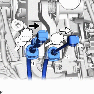
| *1 | Select Control Cable |
| *2 | Shift Control Cable |
Connect the shift control cable and select control cable to the shift lever assembly.
for Transmission Assembly Side:
Engage the 4 claws to install the 2 new clips to the transmission control cable assembly.
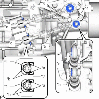
| *1 | Transmission Control Cable Assembly |
| *2 | No. 3 Transmission Control Cable Bracket |
| *3 | Cable Rod |
| *4 | Clip |
| *5 | Boot |
| *a | Claw (A) |
| *b | Claw (B) |
| *c | Marking (Red) |
| *d | Marking (Blue) |
| *e | Cable End Washer |
Using a screwdriver, engage the 8 claws and install the transmission control cable assembly to the No. 3 transmission control cable bracket.
- NOTICE:
- ·
Do not apply an excessive load to the transmission control cable assembly. In particular, make sure not to bend or pull the cable rod part by hand.
·Align with the marking and install the transmission control cable assembly to the No. 3 transmission control cable bracket as shown in the illustration.
·Install so that the cable end washer side faces the clip installation side.
·Make sure that the claws (A) of the clip are securely engaged in the grooves of the bracket.
·Make sure that the transmission control cable assembly is securely installed inside of the claws (B) of the clip.
Connect the transmission control cable assembly to the transmission control shaft lever with the 2 clips.
- NOTICE:
- ·
Install so that the clip is inserted from the bottom of the vehicle towards the top of the vehicle.
·After installing, check that the boot is not twisted.
Adjust Transmission Control Cable Assembly:
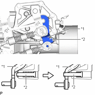
| *1 | Outer Lever |
| *2 | Pin |
Push out the pin and hook it on the outer lever.
- NOTICE:
-
If the transmission control cable assembly is adjusted without hooking the pin on the outer lever, catching may occur during shifting.
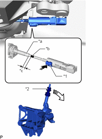
| *1 | Lock Piece |
| *2 | Pull Collar |
| *a | Rod Guide |
| *b | Black Marking |
| *c | 3 to 9 mm (0.119 to 0.354 in.) |
|
|
Push In |
|
|
If the shift lever is not continuously held in the reverse direction without pulling the pull collar to lock the cable length adjustment mechanism, this may cause catching during shifting. |
When reusing the shift lever assembly:
While holding the shift lever in the reverse direction without pulling the pull collar, lock the cable length adjustment mechanism of the select control cable.
- Standard Force in Reverse Direction:
20 N (2 kgf, 4.5 lbf)
- NOTICE:
- ·
Check that the gap between the rod guide and black marking is 3 to 9 mm (0.119 to 0.354 in.).
·If the shift lever is not continuously held in the reverse direction without pulling the pull collar to lock the cable length adjustment mechanism, this may cause catching during shifting.
·If the force in the reverse direction is too large or too small, the adjustment cannot be performed properly.
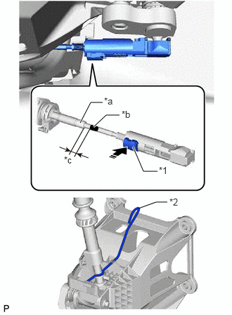
| *1 | Lock Piece |
| *2 | Stopper Spring |
| *a | Rod Guide |
| *b | Black Marking |
| *c | 3 to 9 mm (0.119 to 0.354 in.) |
|
|
Push In |
When replacing the shift lever assembly with a new one:
While holding the shift lever in the reverse direction, lock the cable length adjustment mechanism of the select control cable.
- NOTICE:
-
Check that the gap between the rod guide and black marking is 3 to 9 mm (0.119 to 0.354 in.).
Remove the stopper spring used to prevent improper installation from the shift lever assembly.
- HINT:
-
The stopper spring used to prevent improper installation is only included with supply parts.
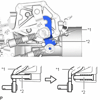
| *1 | Outer Lever |
| *2 | Pin |
After adjusting the transmission control cable assembly, move the shift lever to reverse and disconnect the outer lever from the pin.
33825
3.INSTALL TRANSMISSION CONTROL CABLE INSULATOR (for 7GR-FKS)
87211
4.INSTALL NO. 1 AIR DUCT (for RHD)
87211
5.INSTALL NO. 1 AIR DUCT (for LHD)
55314A
6.INSTALL CENTER LOWER INSTRUMENT PANEL