1GD-FTV ENGINE MECHANICAL CYLINDER HEAD GASKET INSTALLATION
CAUTION / NOTICE / HINT
- NOTICE:
- ·
When replacing the parts in the following chart (A), replace the No. 1 injection pipe sub-assembly, No. 2 injection pipe sub-assembly and/or fuel inlet pipe sub-assembly with new ones.
Replaced Parts (A) Pipes Requiring New Replacement Injector assembly (including shuffling the injector assemblies between the cylinders) ·No. 1 injection pipe sub-assembly
·No. 2 injection pipe sub-assembly
Supply pump assembly Fuel inlet pipe sub-assembly ·Common rail assembly
·Cylinder block sub-assembly
·Cylinder head sub-assembly
·Cylinder head gasket
·Timing chain case assembly
·No. 1 injection pipe sub-assembly
·No. 2 injection pipe sub-assembly
·Fuel inlet pipe sub-assembly
·After removing the No. 1 injection pipe sub-assembly, No. 2 injection pipe sub-assembly and/or fuel inlet pipe sub-assembly, clean them with a brush and compressed air.
·The injector assembly is a precision instrument. Do not use the injector assembly if it is struck or dropped.
·The supply pump assembly is a precision instrument. Do not use the supply pump assembly if it is struck or dropped.
·The common rail assembly is a precision instrument. Do not use the common rail assembly if it is struck or dropped.
·Hold the supply pump assembly itself during removal and installation. Do not hold the pre-stroke control valve or fuel pipe, etc.
·Hold the common rail assembly itself during removal and installation. Do not hold the pressure discharge valve or fuel pressure sensor, etc.
·Make sure foreign matter does not enter the fuel path.
PROCEDURE

 11115
1.INSTALL CYLINDER HEAD GASKET
Check the piston protrusions for each cylinder.
Clean the cylinder block sub-assembly with solvent.
Set the piston of the cylinder to measure to a position slightly before TDC.
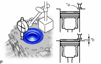
| *a | Measuring Tip |
| *b | Protrusion |
Place a dial indicator on the cylinder block sub-assembly, and position the measuring tip as shown in the illustration.
Set the dial indicator at 0 mm (0 in.)
- HINT:
-
Make sure that the measuring tip is square to the cylinder block gasket surface and piston head when taking the measurements.
Find where the piston head protrudes most by slowly turning the crankshaft clockwise and counterclockwise.
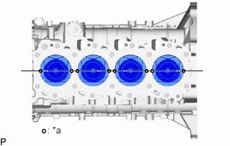
| *a | Measuring Point |
Measure the piston protrusion of each cylinder at the 2 points shown in the illustration.
For the piston protrusion value of each cylinder, use the average of the 2 measurements of each cylinder.
- Standard piston protrusion:
0.355 to 0.605 mm (0.0140 to 0.0238 in.)
- HINT:
-
When installing the piston and connecting rod assembly, if the protrusion is not as specified, remove the piston and connecting rod assembly and reinstall them.
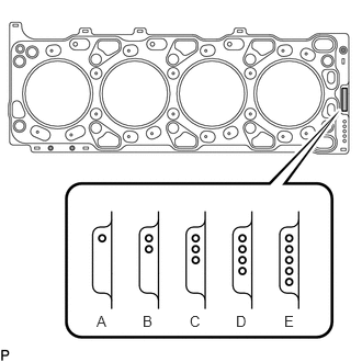
Select a new cylinder head gasket.
- HINT:
-
New cylinder head gaskets are available in 5 sizes, and are marked A, B, C, D or E.
| Mark | Specified Condition |
|---|---|
| A | 1.15 to 1.25 mm (0.0453 to 0.0492 in.) |
| B | 1.20 to 1.30 mm (0.0472 to 0.0512 in.) |
| C | 1.25 to 1.35 mm (0.0492 to 0.0531 in.) |
| D | 1.30 to 1.40 mm (0.0512 to 0.0551 in.) |
| E | 1.35 to 1.45 mm (0.0531 to 0.0571 in.) |
Select the largest piston protrusion value from the measurements made. Then select a new appropriate cylinder head gasket according to the table below.
| Item | Specified Condition | ||||
|---|---|---|---|---|---|
| Piston protrusion | 0.355 to 0.405 mm (0.0140 to 0.0159 in.) | 0.405 to 0.455 mm (0.0159 to 0.0179 in.) | 0.455 to 0.505 mm (0.0179 to 0.0199 in.) | 0.505 to 0.555 mm (0.0199 to 0.0219 in.) | 0.555 to 0.605 mm (0.0219 to 0.0238 in.) |
| Gasket to be used | A | B | C | D | E |
Clean and degrease the contact surfaces of the cylinder head sub-assembly and cylinder block sub-assembly.
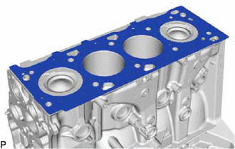
Place the cylinder head gasket on the cylinder block sub-assembly.
- NOTICE:
-
Make sure the cylinder head gasket is installed facing the proper direction.
11101
2.INSTALL CYLINDER HEAD SUB-ASSEMBLY
- HINT:
- ·
If any cylinder head set bolt is broken or deformed, replace the cylinder head set bolt and cylinder head set bolt spacer.
·The cylinder head set bolts are tightened in 3 progressive steps.
Clean and degrease the contact surfaces of the cylinder head sub-assembly and cylinder block sub-assembly.
Place the cylinder head sub-assembly on the cylinder head gasket.
Apply a light coat of engine oil to the threads and under the heads of the cylinder head set bolts.
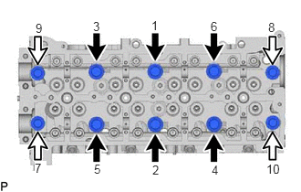

|
Bolt A |

|
Bolt B |
Install and uniformly tighten the 10 cylinder head set bolts and 6 cylinder head set bolt spacers in several passes in the sequence shown in the illustration.
- Torque:
- for bolt A : 150 N*m (1530 kgf*cm, 111 ft.*lbf)
- for bolt B : 85 N*m (867 kgf*cm, 63 ft.*lbf)
| Item | Specified Condition |
|---|---|
| Bolt A | 180 mm (7.09 in.) |
| Bolt B | 127 mm (5.00 in.) |
If any of the cylinder head set bolts does not meet the specification, replace it.
Mark the front of each cylinder head set bolt with paint.
Further tighten the cylinder head set bolts by 90° in the sequence shown in the illustration above.
Finally, tighten the cylinder head set bolts by an additional 90°.
Check that the painted marks are now facing rearward.
13750
3.INSTALL VALVE LASH ADJUSTER ASSEMBLY
13801
4.INSTALL NO. 1 VALVE ROCKER ARM SUB-ASSEMBLY
11310
5.INSTALL TIMING CHAIN COVER ASSEMBLY
6.INSTALL CAMSHAFT
w/ EGR Cooler:
Click hereEngine / Hybrid System>1GD-FTV (ENGINE MECHANICAL)>CAMSHAFT (w/ EGR Cooler)>INSTALLATION
w/o EGR Cooler:
Click hereEngine / Hybrid System>1GD-FTV (ENGINE MECHANICAL)>CAMSHAFT (w/o EGR Cooler)>INSTALLATION