1GD-FTV FUEL FUEL TANK REMOVAL
CAUTION / NOTICE / HINT
The necessary procedures (adjustment, calibration, initialization or registration) that must be performed after parts are removed and installed, or replaced during fuel tank assembly removal/installation are shown below.
| Replaced Part or Performed Procedure | Necessary Procedure | Effect/Inoperative Function when Necessary Procedure not Performed | Link |
|---|---|---|---|
| Battery terminal is disconnected/reconnected | Memorize steering angle neutral point | Parking assist monitor system | ( ) |
- HINT:
-
When the cable is disconnected / reconnected to the battery terminal, systems temporarily stop operating. However, each system has a function that completes learning the first time the system is used.
- ·
Learning completes when vehicle is driven
Effect/Inoperative when not Performed Necessary Procedures Link Stop and start system Drive the vehicle until stop and start control is permitted (approximately 5 to 60 minutes). ( )
Lane control system Drive the vehicle straight ahead at 15 km/h (10 mph) or more for 1 second or more. ( )
Pre-collision system
·Learning completes when vehicle is operated normally
Effect/Inoperative when not Performed Necessary Procedures Link Power slide door system Fully close the slide door by hand.
- HINT:
-
Initialization is not necessary if the above procedures are performed while the slide door is closed.
( )
Air conditioning system After the ignition switch is turned to ON, the servo motor standard position is recognized. -
- CAUTION:
- ·
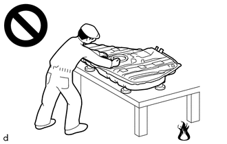
Never perform work on fuel system components near any possible ignition sources.
·Vaporized fuel could ignite, resulting in a serious accident.
- ·
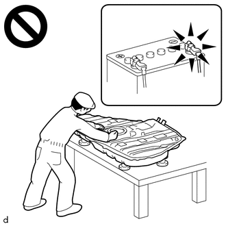
Do not perform work on fuel system components without first disconnecting the cable from the negative (-) battery terminal.
·Sparks could cause vaporized fuel to ignite, resulting in a serious accident.
·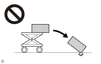
The fuel tank assembly is very heavy. Be sure to follow the procedure described in the repair manual, or the fuel tank assembly may fall off the engine lifter.
PROCEDURE

 1. PRECAUTION
- NOTICE:
-
After turning the ignition switch is turned off, there may be a waiting time before disconnecting the negative (-) battery terminal.
-
Click hereGeneral>SETUP>WHEN DISCONNECTING OR RECONNECTING BATTERY TERMINAL>BEFORE DISCONNECTING BATTERY
2.DISCONNECT CABLE FROM NEGATIVE BATTERY TERMINAL
77310A
3.REMOVE FUEL TANK CAP ASSEMBLY
51495
4.REMOVE TRANSMISSION UNDER COVER (w/ Cover)
51408B
5.REMOVE ENGINE UNDER COVER SUB-ASSEMBLY RH (w/ Cover)
77276
6.REMOVE FUEL HOSE PROTECTOR (w/o Cover)
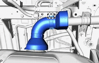
Detach the clamp and remove the fuel hose protector from the fuel tank to fuel filler pipe hose.
77209C
7.DISCONNECT FUEL TANK MAIN TUBE SUB-ASSEMBLY AND FUEL TANK RETURN TUBE
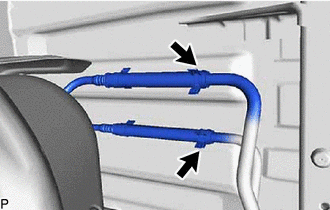
Slide the 2 clamps and disconnect the fuel tank main tube sub-assembly and fuel tank return tube from the 2 fuel pipes.
77213E
8.DISCONNECT FUEL TANK TO FILLER PIPE HOSE
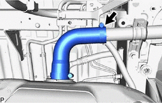
Loosen the clamp and disconnect the fuel tank to filler pipe hose from the fuel tank filler pipe sub-assembly.
9.DISCONNECT FUEL TANK BREATHER HOSE
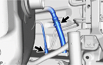
Slide the clamp and disconnect the fuel hose and fuel tank breather hose from the fuel tank filler pipe sub-assembly.
Disconnect the fuel tank vent tube sub-assembly from the vehicle body.
10.REMOVE FUEL TANK ASSEMBLY
- CAUTION:
-
The fuel tank assembly is very heavy. Be sure to follow the procedure described in the repair manual, or the fuel tank assembly may fall off the engine lifter.
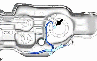
Disconnect the fuel sender gauge connector from the fuel tank vent tube assembly.
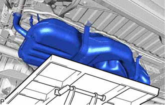
Using an engine lifter and attachments, support the fuel tank assembly.
- HINT:
-
Using height adjustment attachments and plate lift attachments, keep the fuel tank assembly horizontal.
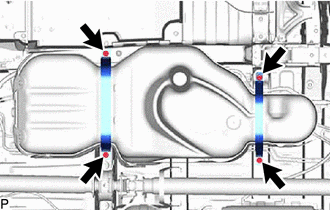
Remove the 4 bolts and disconnect the 2 fuel tank bands.
77697
11.REMOVE NO. 1 FUEL TANK HEAT INSULATOR
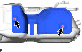
Remove the 2 nuts and No. 1 fuel tank heat insulator from the fuel tank assembly.
77697A
12.REMOVE NO. 2 FUEL TANK HEAT INSULATOR
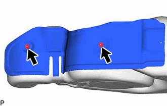
Remove the 2 nuts and No. 2 fuel tank heat insulator from the fuel tank assembly.
77651A
13.REMOVE FUEL TANK CUSHION
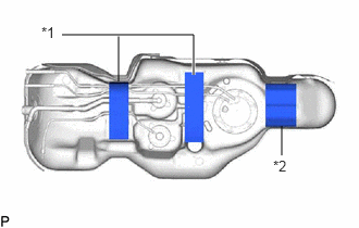
| *1 | No. 1 Fuel Tank Cushion |
| *2 | No. 2 Fuel Tank Cushion |
Remove the 2 No. 1 fuel tank cushions and No. 2 fuel tank cushion from the fuel tank assembly.
77285R
14.REMOVE NO. 1 FUEL TUBE CLAMP
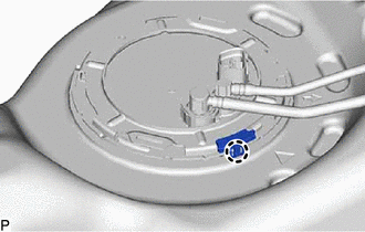
Detach the claw and remove the No. 1 fuel tube clamp.
77010
15.REMOVE FUEL TANK VENT TUBE ASSEMBLY
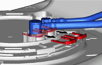
Remove the 2 tube joint clips and pull out the fuel tank main tube sub-assembly and fuel tank return tube from the fuel tank vent tube assembly.
- NOTICE:
-
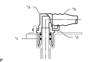 1.167,0.25 1.25,0.25 1.25,0.25 1.417,0.5 true 2.25,0.5 2.417,0.333 2.417,0.333 2.5,0.333 true 2.083,1.063 2.417,1.313 2.417,1.313 2.583,1.313 true 0.927,1.365 0.927,1.198 0.927,1.198 1.427,1.198 true 0.76,1.365 1.427,1.365 true 0.938,0.167 1.156,0.344 0.219,0.177 10 false *a 2.563,0.24 2.781,0.406 0.219,0.167 10 false *b 0.531,1.271 0.74,1.448 0.208,0.177 10 false *c 2.646,1.229 2.875,1.406 0.229,0.177 10 false *d
*a Fuel Tube Joint *b Fuel Tube *c O-Ring *d Tube Joint Clip
- ·
Remove any dirt and foreign matter on the fuel tube joint before performing this work.
·Do not allow any scratches or foreign matter on the parts when disconnecting them, as the fuel tube joint contains the O-rings that seal the plug.
·Perform this work by hand. Do not use any tools.
·Do not forcibly bend or twist the nylon tube.
·Protect the disconnected parts by covering them with plastic bags and tape after disconnecting the fuel tank main tube sub-assembly and fuel tank return tube.
Remove the fuel pump gauge retainer from the fuel tank assembly.
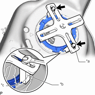
| *a | SST (Plate) |
| *b | SST (Claw) |
| *c | Insertion point |

|
SST (Bolt) |
Set the 2 claws, 2 bolts and plate of SST on the fuel pump gauge retainer.
- SST
- 09808-14031 (09808-01010, 09808-01030, 09808-01090)
09808-01110
- HINT:
-
Securely insert the ends of SST into the insertion points in the fuel pump gauge retainer.
While firmly pressing the claws of SST into the insertion points in the fuel pump gauge retainer, tighten the bolts of the claws.
Attach the handle of SST.
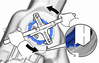
| *a | Insertion point |
Check once more that the tip of SST is securely inserted into the insertion area of the fuel pump gauge retainer as shown in the illustration.
While lightly pressing down on SST so it does not come off the fuel pump gauge retainer, slowly turn the handle and remove the fuel pump gauge retainer.
- NOTICE:
- ·
Do not use any tools other than SST, such as a screwdriver, etc.
·Do not use excessive force when pressing down on SST, as the fuel pump gauge retainer will place excessive force on the fuel tank vent tube assembly and fuel pump gauge retainer and be difficult to remove, and parts may be damaged.
·Be sure to keep the handle level when turning it, as SST may slip off the fuel pump gauge retainer if the handle is turned at an angle with excessive force.
·Do not use an impact wrench or turn the handle with excessive force, as parts may be damaged.
·If SST slips off the fuel pump gauge retainer, loosen the bolts and reattach SST to the fuel pump gauge retainer.
Remove the fuel tank vent tube assembly from the fuel tank sub-assembly.
- NOTICE:
-
Be careful not to bend the arm of the fuel sender gauge assembly.
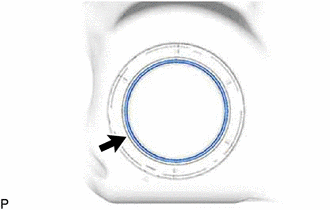
Remove the fuel tank vent tube gasket from the fuel tank sub-assembly.
77204A
16.REMOVE FUEL TANK RETURN TUBE
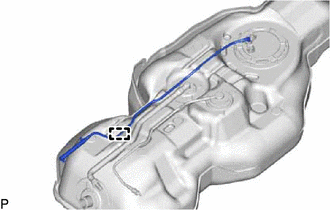
Detach the clamp and remove the fuel tank return tube from the fuel tank assembly.
77209C
17.REMOVE FUEL TANK MAIN TUBE SUB-ASSEMBLY
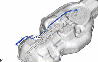
Detach the clamp and remove the fuel tank main tube sub-assembly from the fuel tank assembly.
77213E
18.REMOVE FUEL TANK TO FILLER PIPE HOSE
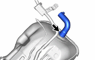
Loosen the clamp and remove the fuel tank to filler pipe hose from the fuel tank sub-assembly.