RC60J MANUAL TRANSMISSION / TRANSAXLE SHIFT AND SELECT TRANSMISSION CONTROL CABLE ADJUSTMENT
CAUTION / NOTICE / HINT
- NOTICE:
-
The stopper spring used to prevent improper installation that is included with the shift lever supply part is removed in the transmission control cable assembly adjustment procedure.
PROCEDURE

 1.SECURE VEHICLE
Fully apply the parking brake and chock a wheel.
- CAUTION:
-
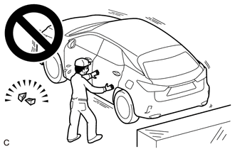
- ·
Make sure to apply the parking brake and chock a wheel before performing this procedure.
·If the vehicle is not secure and the shift lever is moved to N, the vehicle may suddenly move, possibly resulting in an accident or serious injury.
55314A
2.REMOVE CENTER LOWER INSTRUMENT PANEL
87211
3.REMOVE NO. 1 AIR DUCT (for LHD)
87211
4.REMOVE NO. 1 AIR DUCT (for RHD)
33820B
5.ADJUST TRANSMISSION CONTROL CABLE ASSEMBLY
- NOTICE:
-
Do not bend the transmission control cable assembly within a radius of 120 mm (4.72 in.).
- HINT:
- ·
After the shift lever or the shift control cable is replaced, be sure to adjust the transmission control cable assembly.
·If the shift lever does not move (or the shift lever is difficult to move) to the 1st or 2nd position, or if it is possible to move the shift lever to reverse without pulling up the slider shaft, the length of the cable must be adjusted.
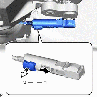
| *1 | Slider |
| *2 | Lock Piece |

|
Slide in this Direction |

|
Pull Out |
Slide the slider in the direction shown in the illustration and pull out the lock piece.
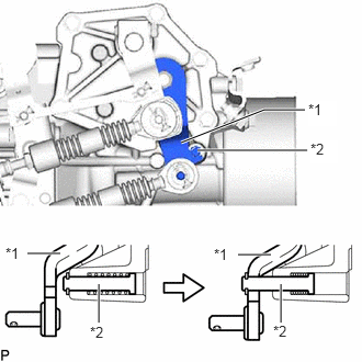
| *1 | Outer Lever |
| *2 | Pin |
Push out the pin and hook it on the outer lever.
- NOTICE:
-
If the transmission control cable assembly is adjusted without hooking the pin on the outer lever, catching may occur during shifting.
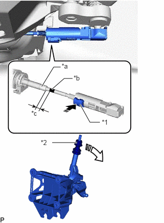
| *1 | Lock Piece |
| *2 | Pull Collar |
| *a | Rod Guide |
| *b | Black Marking |
| *c | 3 to 9 mm (0.119 to 0.354 in.) |
|
|
Push In |
|
|
If the shift lever is not continuously held in the reverse direction without pulling the pull collar to lock the cable length adjustment mechanism, this may cause catching during shifting. |
When reusing the shift lever assembly:
While holding the shift lever in the reverse direction without pulling the pull collar, lock the cable length adjustment mechanism of the select control cable.
- Standard Force in Reverse Direction:
20 N (2 kgf, 4.5 lbf)
- NOTICE:
- ·
Check that the gap between the rod guide and black marking is 3 to 9 mm (0.119 to 0.354 in.).
·If the shift lever is not continuously held in the reverse direction without pulling the pull collar to lock the cable length adjustment mechanism, this may cause catching during shifting.
·If the force in the reverse direction is too large or too small, the adjustment cannot be performed properly.
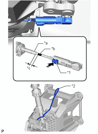
| *1 | Lock Piece |
| *2 | Stopper Spring |
| *a | Rod Guide |
| *b | Black Marking |
| *c | 3 to 9 mm (0.119 to 0.354 in.) |
|
|
Push In |
When replacing the shift lever assembly with a new one:
While holding the shift lever in the reverse direction, lock the cable length adjustment mechanism of the select control cable.
- NOTICE:
-
Check that the gap between the rod guide and black marking is 3 to 9 mm (0.119 to 0.354 in.).
Remove the stopper spring used to prevent improper installation from the shift lever assembly.
- HINT:
-
The stopper spring used to prevent improper installation is only included with supply parts.
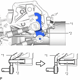
| *1 | Outer Lever |
| *2 | Pin |
After adjusting the transmission control cable assembly, move the shift lever to reverse and disconnect the outer lever from the pin.
87211
6.INSTALL NO. 1 AIR DUCT (for RHD)
87211
7.INSTALL NO. 1 AIR DUCT (for LHD)
55314A
8.INSTALL CENTER LOWER INSTRUMENT PANEL