PARK ASSIST / MONITORING CLEARANCE WARNING ECU INSTALLATION
CAUTION / NOTICE / HINT
- HINT:
- ·
Use the same procedure for RHD and LHD vehicles.
·The procedure listed below is for LHD vehicles.
·A bolt without a torque specification is shown in the standard bolt chart.
Click hereGeneral>SPECIFICATIONS>STANDARD BOLT>SPECIFIED TORQUE FOR STANDARD BOLTS
PROCEDURE

 89340A
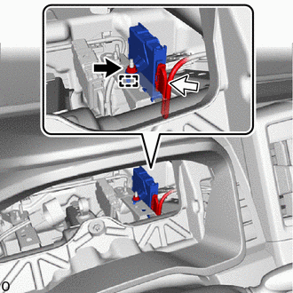
1.INSTALL CLEARANCE WARNING ECU ASSEMBLY

|
Nut |

|
Connector |
Connect the connector.
Attach the hook and install the clearance warning ECU assembly with the nut.
86792C
2.INSTALL PARKING ASSIST ECU (w/ Panoramic View Monitor System)
88051B
3.INSTALL NO. 1 ION GENERATOR SUB-ASSEMBLY (w/ Ion Generator)
83100
4.INSTALL COMBINATION METER ASSEMBLY
5.CONNECT CABLE TO NEGATIVE BATTERY TERMINAL (w/ Panoramic View Monitor System)
for 7GR-FKS:
for 1GD-FTV:
6. INITIALIZATION AFTER RECONNECTING BATTERY TERMINAL (w/ Panoramic View Monitor System)
Click hereGeneral>SETUP>WHEN DISCONNECTING OR RECONNECTING BATTERY TERMINAL>WORK PROCEDURE
- HINT:
-
When disconnecting and reconnecting the battery, there is an automatic learning function that completes learning when the respective system is used.
-
Click hereGeneral>SETUP>WHEN DISCONNECTING OR RECONNECTING BATTERY TERMINAL>AUTOMATIC LEARNING CHART
7.PERFORM DIAGNOSTIC SYSTEM CHECK (w/ Panoramic View Monitor System)
8.CHECK SRS WARNING LIGHT (w/ Panoramic View Monitor System)