FRONT SUSPENSION FRONT LOWER SUSPENSION ARM REMOVAL
CAUTION / NOTICE / HINT
The necessary procedures (adjustment, calibration, initialization, or registration) that must be performed after parts are removed and installed, or replaced during front lower No. 1 suspension arm sub-assembly removal/installation are shown below.
| Replaced Part or Performed Procedure | Necessary Procedure | Effect/Inoperative Function when Necessary Procedure not Performed | Link |
|---|---|---|---|
| Front wheel alignment adjustment | ·
Perform reset memory ·
Perform acceleration sensor zero point calibration and store system information memorization. |
·
VSC is disabled or malfunctions ·
DTCs are output ·
Slip indicator light illuminates ·
ABS warning light illuminates |
( ) |
| Suspension, tires, etc. | Television camera assembly optical axis (Back camera position setting) | Parking assist monitor system | ()
|
·
Parking assist ECU initialization ·
Adjust steering angle |
Panoramic view monitor system | ()
|
|
| Replacement of the rear height control sensor sub-assembly LH, removal and reinstallation of the rear height control sensor sub-assembly LH, replacement of the suspension, etc. have been performed | Perform headlight ECU sub-assembly LH initialization | Lighting system (EXT) | ()
|
- HINT:
- ·
Use the same procedure for the RH side and LH side.
·The following procedure is for the LH side.
PROCEDURE

 1.REMOVE FRONT WHEEL
51406A
2.REMOVE NO. 2 ENGINE UNDER COVER SUB-ASSEMBLY (w/ No. 2 Engine Under Cover Sub-assembly)
for 7GR-FKS:
Click hereEngine / Hybrid System>7GR-FKS (ENGINE MECHANICAL)>ENGINE ASSEMBLY>REMOVAL
for 1GD-FTV:
Click hereEngine / Hybrid System>1GD-FTV (ENGINE MECHANICAL)>ENGINE ASSEMBLY>REMOVAL
52618
3.REMOVE LOWER FRONT BUMPER ABSORBER
for 7GR-FKS:
Click hereEngine / Hybrid System>7GR-FKS (ENGINE MECHANICAL)>ENGINE ASSEMBLY>REMOVAL
for 1GD-FTV:
Click hereEngine / Hybrid System>1GD-FTV (ENGINE MECHANICAL)>ENGINE ASSEMBLY>REMOVAL
51405A
4.REMOVE NO. 1 ENGINE UNDER COVER SUB-ASSEMBLY
for 7GR-FKS:
Click hereEngine / Hybrid System>7GR-FKS (ENGINE MECHANICAL)>ENGINE ASSEMBLY>REMOVAL
for 1GD-FTV:
Click hereEngine / Hybrid System>1GD-FTV (ENGINE MECHANICAL)>ENGINE ASSEMBLY>REMOVAL
51495
5.REMOVE TRANSMISSION UNDER COVER (w/ Transmission Under Cover)
for 1GD-FTV:
Click hereEngine / Hybrid System>1GD-FTV (EMISSION CONTROL)>UREA TANK>REMOVAL
51408B
6.REMOVE ENGINE UNDER COVER SUB-ASSEMBLY RH (w/ Engine Under Cover Sub-assembly RH)
for 1GD-FTV:
Click hereEngine / Hybrid System>1GD-FTV (ENGINE MECHANICAL)>ENGINE ASSEMBLY>REMOVAL
51108C
7.REMOVE REAR SIDE RAIL REINFORCEMENT SUB-ASSEMBLY
for 7GR-FKS:
Click hereEngine / Hybrid System>7GR-FKS (ENGINE MECHANICAL)>ENGINE ASSEMBLY>REMOVAL
for 1GD-FTV:
Click hereEngine / Hybrid System>1GD-FTV (ENGINE MECHANICAL)>ENGINE ASSEMBLY>REMOVAL
45047
8.DISCONNECT TIE ROD END SUB-ASSEMBLY
for LHD:
Click hereSteering>STEERING GEAR / LINKAGE>STEERING GEAR (for LHD)>REMOVAL
for RHD:
Click hereSteering>STEERING GEAR / LINKAGE>STEERING GEAR (for RHD)>REMOVAL
89543
9.DISCONNECT FRONT SPEED SENSOR
10.DISCONNECT FRONT DISC BRAKE CALIPER ASSEMBLY
43512
11.REMOVE FRONT DISC
Click hereBrake>BRAKE (FRONT)>FRONT BRAKE>REMOVAL
43212
12.DISCONNECT STEERING KNUCKLE
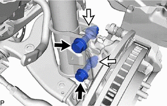
Remove the 2 bolts, 2 nuts and disconnect the steering knuckle from the front shock absorber assembly.
- NOTICE:
-
When removing the nuts, keep the bolts from rotating.
48069
13.DISCONNECT FRONT LOWER NO. 1 SUSPENSION ARM SUB-ASSEMBLY
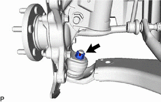
Remove the cotter pin.
Remove the nut.
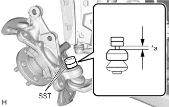
| *a | 1 mm (0.0394 in.) |
Install SST to the front lower No. 1 suspension arm sub-assembly as shown in the illustration.
- SST
- 09961-02080
- NOTICE:
-
Check that the clearance measurement between SST and the steering knuckle is 1 mm (0.0394 in.).
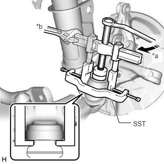
| *a | Turn |
| *b | Hold |
Using SST, disconnect the front lower No. 1 suspension arm sub-assembly from the steering knuckle.
- SST
- 09950-40011 (09951-04010, 09952-04010, 09953-04020, 09954-04010, 09955-04031, 09957-04010, 09958-04011)
- NOTICE:
- ·
Before using the SST center bolt (09953-04020), apply grease to its threads and tip.
·Do not damage the dust cover.
43212
14.TEMPORARILY INSTALL STEERING KNUCKLE
Temporarily install the steering knuckle to the from the front shock absorber assembly with the 2 bolts and 2 nuts.
- NOTICE:
- ·
Insert the bolt from the front of the vehicle.
·When installing the bolts, keep the nuts from rotating.
·Do not apply lubricants to the steering knuckle and shock absorber contact surfaces.
48069
15.REMOVE FRONT LOWER NO. 1 SUSPENSION ARM SUB-ASSEMBLY
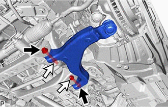
Remove the 2 bolts, 2 nuts and front lower No. 1 suspension arm sub-assembly from the front frame assembly.