1GD-FTV EMISSION CONTROL EXHAUST FUEL ADDITION INJECTOR INSTALLATION
PROCEDURE

 23710B
1.INSTALL EXHAUST FUEL ADDITION INJECTOR ASSEMBLY
Install a new No. 1 fuel injector back-up ring, No. 2 fuel injector back-up ring, O-ring and No. 3 fuel injector back-up ring to the exhaust fuel addition injector assembly.
Install a new E-ring to the exhaust fuel addition injector assembly.
Install a new gasket and the exhaust fuel addition injector assembly to the No. 1 injector holder.
23695B
2.INSTALL NO. 2 NOZZLE HOLDER CLAMP
Using a T40 "TORX" socket wrench, install the No. 2 nozzle holder clamp with the bolt.
- Torque:
- 11.5 N*m (117 kgf*cm, 8 ft.*lbf)
23295C
3.INSTALL INJECTOR HOLDER
Install the injector holder to the No. 1 injector holder with the 2 bolts.
- Torque:
- 10 N*m (102 kgf*cm, 7 ft.*lbf)
17168
4.INSTALL NO. 2 EXHAUST MANIFOLD HEAT INSULATOR
Install a new gasket and the No. 2 exhaust manifold heat insulator to the No. 1 injector holder with the 3 nuts.
- Torque:
- 10 N*m (102 kgf*cm, 7 ft.*lbf)
23295D
5.INSTALL NO. 1 INJECTOR HOLDER
Install the No. 1 injector holder to the exhaust manifold with 3 new nuts.
- Torque:
- 43 N*m (438 kgf*cm, 32 ft.*lbf)
Connect the connector to the exhaust fuel addition injector assembly.
16282
6.CONNECT NO. 5 WATER BY-PASS HOSE
Connect the No. 5 water by-pass hose to the No. 1 injector holder, and slide the clamp to secure the hose.
16281
7.CONNECT NO. 4 WATER BY-PASS HOSE
Connect the No. 4 water by-pass hose to the No. 1 injector holder, and slide the clamp to secure the hose.
12229
8.INSTALL PCV PIPE
23811H
9.INSTALL NO. 1 FUEL PIPE
Connect the No. 1 fuel pipe to the No. 4 fuel pipe.
Click hereEngine / Hybrid System>1GD-FTV (FUEL)>FUEL SYSTEM>PRECAUTION
for Air Cooled Type Intercooler:
Install a new gasket and the No. 1 fuel pipe to the cylinder head cover sub-assembly and No. 1 injector holder with the union bolt and bolt.
- Torque:
- for bolt : 10 N*m (102 kgf*cm, 7 ft.*lbf)
- for union bolt : 36 N*m (367 kgf*cm, 27 ft.*lbf)
for Water Cooled Type Intercooler:
Install the No. 1 fuel pipe to the cylinder head cover sub-assembly with the bolt.
- Torque:
- 10 N*m (102 kgf*cm, 7 ft.*lbf)
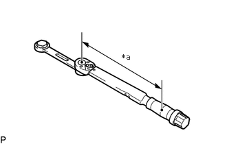
| *a | Torque Wrench Fulcrum Length |
Using a 17 mm ball joint lock nut wrench, install a new gasket and the No. 1 fuel pipe to the No. 1 injector holder with the union bolt.
- Torque:
Specified tightening torque
36 N*m (367 kgf*cm, 27 ft.*lbf)
- HINT:
- ·
Calculate the torque wrench reading when changing the fulcrum length of the torque wrench.
Click hereGeneral>INTRODUCTION>REPAIR INSTRUCTION>PRECAUTION
·When using a ball joint lock nut wrench (fulcrum length of 149 mm (5.8661 in.)) + torque wrench (fulcrum length of 180 mm (7.0866 in.)): 19.7 N*m (201 kgf*cm, 15 ft.*lbf)
17940D
10.INSTALL INTERCOOLER ASSEMBLY (for Water Cooled Type Intercooler)
12601B
11.INSTALL NO. 1 ENGINE COVER SUB-ASSEMBLY (w/ Cover)
12.BLEED AIR FROM FUEL SYSTEM
13.ADD ENGINE COOLANT (for Air Cooled Type Intercooler)
14.INSPECT FOR COOLANT LEAK (for Air Cooled Type Intercooler)