1GD-FTV INTAKE / EXHAUST INTERCOOLER(for Water Cooled Type Intercooler) INSTALLATION
PROCEDURE

 89424D
1.INSTALL INTAKE AIR TEMPERATURE SENSOR (for Intercooler)
89422P
2.INSTALL ENGINE COOLANT TEMPERATURE SENSOR (for Intercooler)
17940D
3.INSTALL INTERCOOLER ASSEMBLY
Install the intercooler assembly with the 4 bolts.
- Torque:
- 10 N*m (102 kgf*cm, 7 ft.*lbf)
Connect the wire harness protector and exhaust sensor clamp bracket to the intercooler assembly with the bolt.
- Torque:
- 13 N*m (133 kgf*cm, 10 ft.*lbf)
Connect the intake air temperature sensor (for Intercooler) connector.
Connect the engine coolant temperature sensor (for Intercooler) connector.
16278
4.INSTALL NO. 2 WATER BY-PASS PIPE
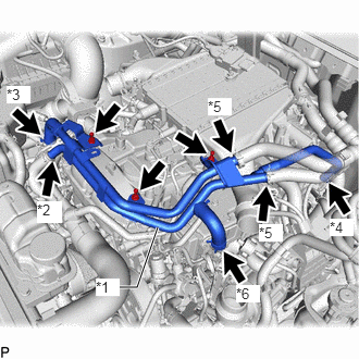
| *1 | No. 2 Water By-pass Pipe |
| *2 | No. 13 Water By-pass Hose |
| *3 | No. 15 Water By-pass Hose |
| *4 | No. 18 Water By-pass Hose |
| *5 | Heater Hose |
| *6 | No. 16 Water By-pass Hose |
Install the No. 2 water by-pass pipe with the 3 bolts.
- Torque:
- 10 N*m (102 kgf*cm, 7 ft.*lbf)
Connect the No. 16 water by-pass hose to the No. 1 EGR cooler, and slide the hose clamp to secure the hose.
Connect the 2 heater hoses to the No. 2 water by-pass pipe, and slide the 2 hose clamps to secure the 2 hoses.
Connect the No. 18 water by-pass hose to the EGR pipe with cooler sub-assembly, and slide the hose clamp to secure the hose.
Connect the No. 15 water by-pass hose to the water by-pass pipe, and slide the hose clamp to secure the hose.
Connect the No. 13 water by-pass hose to the No. 2 water by-pass pipe, and slide the hose clamp to secure the hose.
17030
5.INSTALL AIR HOSE ASSEMBLY
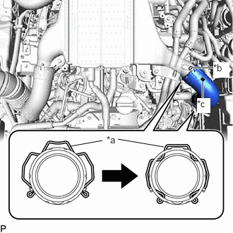
| *a | Retainer |
| *b | Protrusion |
| *c | Stopper |
Connect the air hose assembly to the intercooler assembly and intake air connector and lock the 2 retainers as shown in the illustration.
- NOTICE:
-
Securely insert the retainer so that the 4 locks are engaged. Then, pull and check that the locks are engaged and that the hose cannot be pulled out.
- HINT:
-
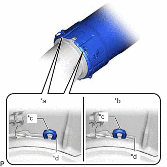 1.167,3.135 1.167,2.854 true 0.76,2.438 0.885,2.438 0.885,2.438 1,2.688 true 2.24,2.406 2.365,2.406 2.365,2.406 2.479,2.656 true 2.771,3.115 2.771,2.833 true 0.823,1.99 1.135,2.146 0.313,0.156 10 false *a 2.354,1.99 2.667,2.146 0.313,0.156 10 false *b 0.563,2.344 0.76,2.531 0.198,0.188 10 true *c 1.083,3.167 1.281,3.354 0.198,0.188 10 true *d 2.031,2.313 2.229,2.5 0.198,0.188 10 true *c 2.688,3.135 2.885,3.323 0.198,0.188 10 true *d
*a Correct *b Incorrect *c Retainer End *d Stopper
- ·
Install so that the protrusion on the intercooler assembly and the stoppers are aligned.
·Make sure that the retainer end contacts the stopper as shown in the illustration.
17360E
6.INSTALL NO. 1 AIR TUBE ASSEMBLY
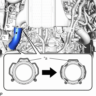
| *a | Retainer |
| *b | Protrusion |
| *c | Stopper |
Connect the No. 1 air tube assembly to the intercooler assembly and compressor outlet elbow and lock the 2 retainers as shown in the illustration.
- NOTICE:
-
Securely insert the retainer so that the 4 locks are engaged. Then, pull and check that the locks are engaged and that the hose cannot be pulled out.
- HINT:
-
1.167,3.135 1.167,2.854 true 0.76,2.438 0.885,2.438 0.885,2.438 1,2.688 true 2.24,2.406 2.365,2.406 2.365,2.406 2.479,2.656 true 2.771,3.115 2.771,2.833 true 0.823,1.99 1.135,2.146 0.313,0.156 10 false *a 2.354,1.99 2.667,2.146 0.313,0.156 10 false *b 0.563,2.344 0.76,2.531 0.198,0.188 10 true *c 1.083,3.167 1.281,3.354 0.198,0.188 10 true *d 2.031,2.313 2.229,2.5 0.198,0.188 10 true *c 2.688,3.135 2.885,3.323 0.198,0.188 10 true *d
*a Correct *b Incorrect *c Retainer End *d Stopper
- ·
Install so that the protrusion on the intercooler assembly and the stoppers are aligned.
·Make sure that the retainer end contacts the stopper as shown in the illustration.
7.INSTALL NO. 2 INTERCOOLER COOLING WATER PIPE ASSEMBLY
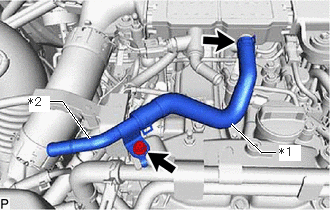
| *1 | No. 5 Intercooler Cooling Water Hose |
| *2 | No. 3 Intercooler Cooling Water Pipe |
Connect the No. 5 intercooler cooling water hose to the No. 3 intercooler cooling water pipe, and slide the hose clamp to secure the hose.
Install the No. 2 intercooler cooling water pipe assembly with the bolt.
- Torque:
- 10 N*m (102 kgf*cm, 7 ft.*lbf)
Connect the No. 5 intercooler cooling water hose to the intercooler assembly, and slide the hose clamp to secure the hose.
16551C
8.CONNECT NO. 1 INTERCOOLER COOLING WATER HOSE
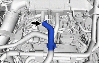
Connect the No. 1 intercooler cooling water hose to the intercooler assembly and slide the hose clamp to secure the hose.
16553D
9.CONNECT NO. 3 INTERCOOLER COOLING WATER HOSE
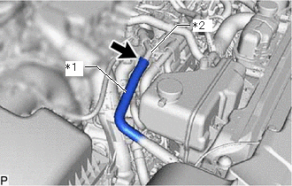
| *1 | No. 3 Intercooler Cooling Water Hose |
| *2 | No. 3 Intercooler Cooling Water Pipe |
Connect the No. 3 intercooler cooling water hose to the No. 3 intercooler cooling water pipe and slide the hose clamp to secure the hose.
12601B
10.INSTALL NO. 1 ENGINE COVER SUB-ASSEMBLY
11.ADD ENGINE COOLANT
12.ADD ENGINE COOLANT (for Intercooler)
13.INSPECT FOR COOLANT LEAK
14.INSPECT FOR COOLANT LEAK (for Intercooler)
51405A
15.INSTALL NO. 1 ENGINE UNDER COVER SUB-ASSEMBLY
52618
16.INSTALL LOWER FRONT BUMPER ABSORBER
51406A
17.INSTALL NO. 2 ENGINE UNDER COVER SUB-ASSEMBLY