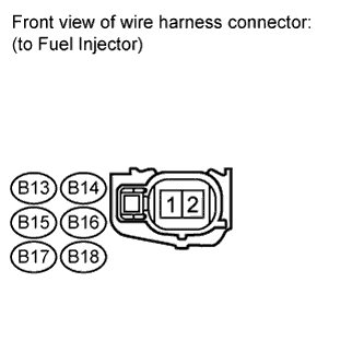
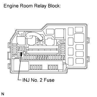
Fuel Injector Circuit
Circuit diagnosis · Vehicles built May 2007 – Jul 2008
Versions by build date: May 2007 – Jul 2008 Aug 2008 – Jun 2010 from Jul 2010
DESCRIPTION
The fuel injectors are located on the intake manifold. They inject fuel into the cylinders based on the signals from the ECM.WIRING DIAGRAM
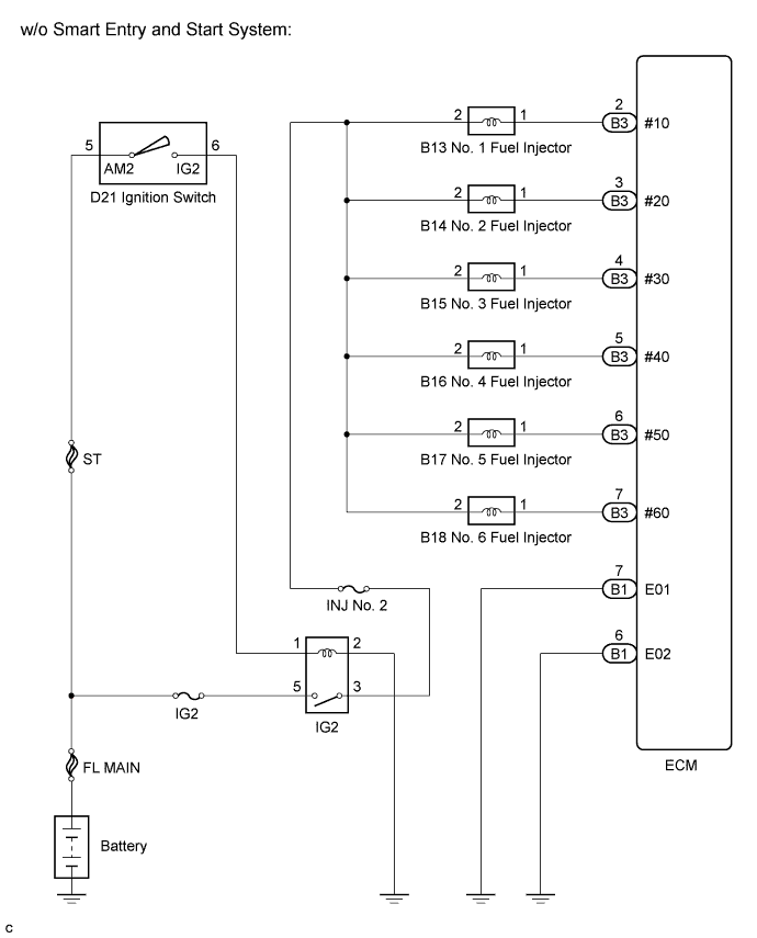

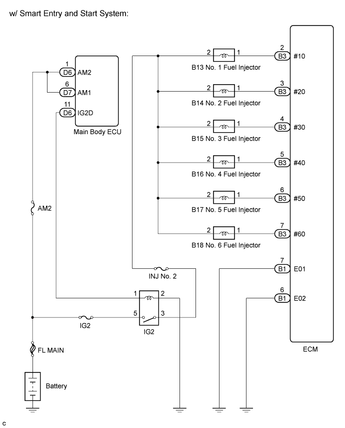
INSPECTION PROCEDURE
| 1. CHECK INJECTOR ASSEMBLY (POWER SOURCE) |
 |
- Disconnect the injector assembly connector.
Turn the ignition switch on (IG).
Measure the voltage according to the value(s) in the table below.
- Standard voltage:
Tester Connection
|
Switch Condition
|
Specified Condition
|
B13-2 - Body ground
|
Ignition switch on (IG)
|
9 to 14 V
|
B14-2 - Body ground
|
Ignition switch on (IG)
|
9 to 14 V
|
B15-2 - Body ground
|
Ignition switch on (IG)
|
9 to 14 V
|
B16-2 - Body ground
|
Ignition switch on (IG)
|
9 to 14 V
|
B17-2 - Body ground
|
Ignition switch on (IG)
|
9 to 14 V
|
B18-2 - Body ground
|
Ignition switch on (IG)
|
9 to 14 V
|
Turn the ignition switch off.
Reconnect the injector assembly connector.
|
NG |
 |
|
|
|
| OK |
|
 |
|
| 2. INSPECT INJECTOR ASSEMBLY |
|
Inspect the injector assembly (Click here).
|
NG |
 |
|
|
|
| OK |
|
|
|
| 3. CHECK HARNESS AND CONNECTOR (INJECTOR ASSEMBLY - ECM) |
|
- Disconnect the injector connector (of the misfiring cylinder).
Measure the voltage according to the value(s) in the table below.
- Standard voltage:
Cylinder
|
Tester Connection
|
Switch Condition
|
Specified Condition
|
No. 1
|
B13-2 - Body ground
|
Ignition switch on (IG)
|
11 to 14 V
|
No. 2
|
B14-2 - Body ground
|
Ignition switch on (IG)
|
11 to 14 V
|
No. 3
|
B15-2 - Body ground
|
Ignition switch on (IG)
|
11 to 14 V
|
No. 4
|
B16-2 - Body ground
|
Ignition switch on (IG)
|
11 to 14 V
|
No. 5
|
B17-2 - Body ground
|
Ignition switch on (IG)
|
11 to 14 V
|
No. 6
|
B18-2 - Body ground
|
Ignition switch on (IG)
|
11 to 14 V
|
|
NG |
|
|
| REPAIR OR REPLACE HARNESS OR CONNECTOR (FUEL INJECTOR ASSEMBLY - ECM) |
|
|
| OK |
|
 |
|
|
| 4. INSPECT FUSE (INJ NO. 2 FUSE) |
|
- Remove the INJ No. 2 fuse from engine room relay block.
Measure the resistance according to the value(s) in the table below.
- Standard resistance:
Tester Connection
|
Condition
|
Specified Condition
|
INJ No. 2 fuse
|
Always
|
Below 1 Ω
|
Reinstall the INJ No. 2 fuse.
|
NG |
|
|
|
|
| OK |
|
|
|
| REPAIR OR REPLACE HARNESS OR CONNECTOR (INTEGRATION RELAY (IG2 RELAY) - FUEL INJECTOR ASSEMBLY) |
|