2007-2013 Highlander Kluger · Service Manual BRAKE

INSTALLATION

Removal / installation · Vehicles built from Jul 2010

Versions by build date: May 2007 – Jul 2008 Aug 2008 – Jun 2010 from Jul 2010

NOTICE:
Before installation, apply high temperature grease to the parts indicated by arrows (Click here).


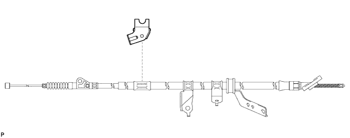
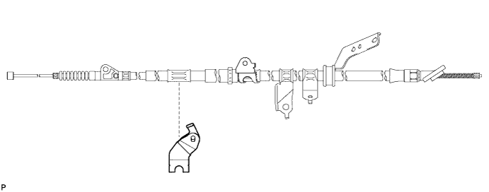
1. INSTALL CABLE SUPPORT BRACKET

  1. Install the cable support bracket to the No. 3 parking brake cable assembly.

    C165719


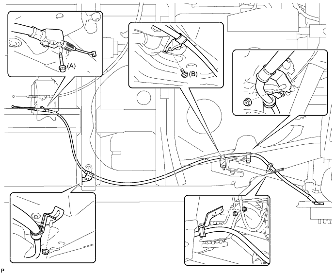
2. INSTALL NO. 3 PARKING BRAKE CABLE ASSEMBLY

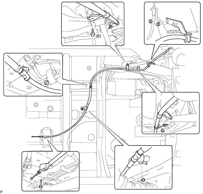
  1. Install the No. 3 parking brake cable assembly with the 2 bolts and 4 nuts.

    C166164E01

    Torque:
    Bolt (A):
    8.5 N*m{ 87 kgf*cm , 75 in.*lbf }
    Bolt (B):
    6.0 N*m{ 61 kgf*cm , 53 in.*lbf }
    Nut:
    6.0 N*m{ 61 kgf*cm , 53 in.*lbf }

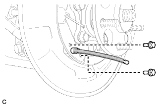
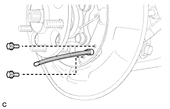
  1. C166156
    Install the No. 3 parking brake cable assembly to the backing plate with the 2 bolts.

    Torque:
    8.0 N*m{ 82 kgf*cm , 71 in.*lbf }


3. INSTALL NO. 1 PARKING BRAKE CABLE SUPPORT BRACKET

  1. Install the No. 1 parking brake cable support bracket to the No. 2 parking brake cable assembly.

    C166585


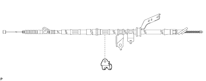
4. INSTALL PARKING BRAKE CABLE SUPPORT BRACKET

  1. Install the parking brake cable support bracket to the No. 2 parking brake cable assembly.

    C166584


5. INSTALL NO. 2 PARKING BRAKE CABLE ASSEMBLY

  1. Install the No. 2 parking brake cable assembly with the 2 bolts and 5 nuts.

    C165718E01

    Torque:
    Bolt (A):
    8.5 N*m{ 87 kgf*cm , 75 in.*lbf }
    Bolt (B):
    6.0 N*m{ 61 kgf*cm , 53 in.*lbf }
    Nut:
    6.0 N*m{ 61 kgf*cm , 53 in.*lbf }

  1. C168094
    Install the No. 2 parking brake cable assembly to the backing plate with the 2 bolts.

    Torque:
    8.0 N*m{ 82 kgf*cm , 71 in.*lbf }


6. APPLY HIGH TEMPERATURE GREASE
  1. Apply high temperature grease to the backing plate which makes contact with the shoe.


7. INSTALL NO. 2 PARKING BRAKE SHOE ASSEMBLY WITH PARKING BRAKE SHOE LEVER

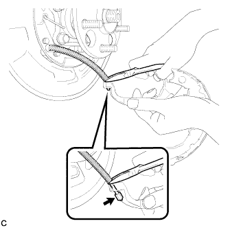
  1. C166155
    Using needle-nose pliers, connect the No. 3 parking brake cable assembly to the parking brake shoe lever as shown in the illustration.


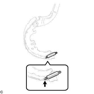
8. INSTALL NO. 2 PARKING BRAKE SHOE RETURN TENSION SPRING

  1. C166153
    Install the No. 2 parking brake shoe return tension spring to the No. 2 parking brake shoe assembly.


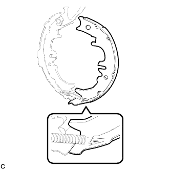
9. INSTALL NO. 1 PARKING BRAKE SHOE ASSEMBLY

  1. C166152
    Connect the No. 2 parking brake shoe return tension spring to install the No. 1 parking brake shoe assembly.


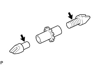
10. INSTALL PARKING BRAKE SHOE ADJUSTING SCREW SET

  1. C132649
    Apply high temperature grease to the parking brake shoe adjusting screw set as shown in the illustration.

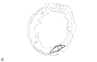
  1. C166151
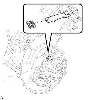
    Install the parking brake shoe adjusting screw set.


11. INSTALL NO. 2 PARKING BRAKE SHOE ASSEMBLY

  1. C166150
    Install the No. 2 parking brake shoe assembly to the backing plate with the No. 1 parking brake shoe hold down spring cup, parking brake shoe hold down spring, and No. 2 parking brake shoe hold down spring cup.


12. INSTALL PARKING BRAKE SHOE STRUT

  1. C166149
    Install the parking brake shoe strut and the parking brake shoe strut compression spring.


13. INSTALL NO. 1 PARKING BRAKE SHOE ASSEMBLY

  1. C166148
    Install the No. 1 parking brake shoe assembly to the backing plate with the No. 1 parking brake shoe hold down spring cup, parking brake shoe hold down spring, and No. 2 parking brake shoe hold down spring cup.


14. INSTALL NO. 1 PARKING BRAKE SHOE RETURN TENSION SPRING

  1. C166147
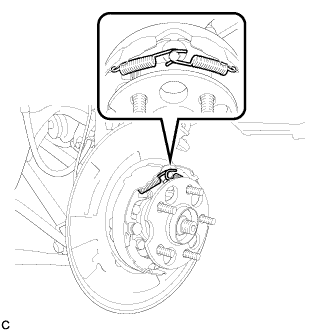
    Install the 2 No. 1 parking brake shoe return tension springs.

    HINT:
    First install the front side spring and then the rear side spring.


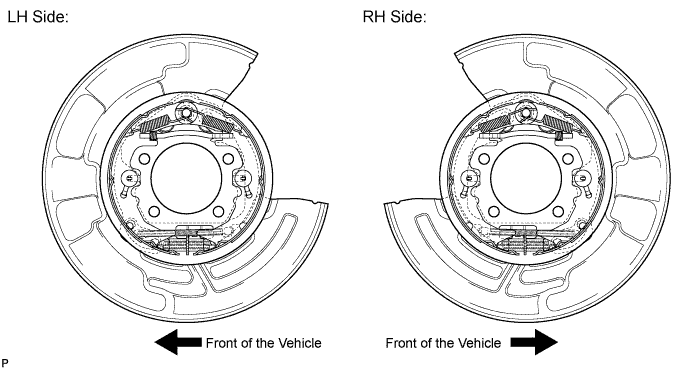
15. CHECK PARKING BRAKE INSTALLATION

  1. Check that each part is installed properly.

    C166165E01

    NOTICE:
    There should be no oil or grease on the friction surface of the shoe lining and disc.


16. INSTALL REAR DISC

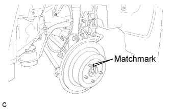
  1. C166438E01
    Align matchmarks and install the rear disc.

    NOTICE:
    When replacing the rear disc with a new one, select the installation position where the rear disc has minimal runout.


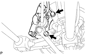
17. INSTALL REAR DISC BRAKE CALIPER ASSEMBLY (for 2WD)

  1. C167785
    Install the rear disc brake caliper assembly with the 2 bolts.

    Torque:
    78 N*m{ 795 kgf*cm , 57 ft.*lbf }


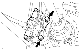
18. INSTALL REAR DISC BRAKE CALIPER ASSEMBLY (for 4WD)

  1. C165996
    Install the rear disc brake caliper assembly with the 2 bolts.

    Torque:
    78 N*m{ 795 kgf*cm , 57 ft.*lbf }


19. INSTALL NO. 1 PARKING BRAKE CABLE ASSEMBLY
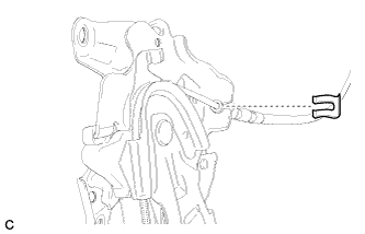
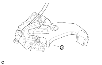
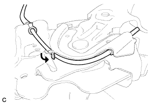
  1. Pass the No. 1 parking brake cable assembly through the parking brake pedal.

  1. C165704
    Install the clip to the No. 1 parking brake cable assembly.

  1. C165703
    Temporarily install the adjusting nut.

  1. C165706
    Bend the parking brake pedal claw.


20. INSTALL PARKING BRAKE CONTROL PEDAL ASSEMBLY

HINT:
Refer to the instructions for INSTALLATION of the parking brake pedal (Click here).


21. ADJUST PARKING BRAKE SHOE CLEARANCE AND PARKING BRAKE PEDAL TRAVEL (for LHD)
  1. Remove the driver side knee airbag assembly (Click here).

  1. Completely release the parking brake pedal.

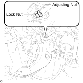
  1. C166160E01
    Loosen the lock nut and the adjusting nut to completely release the parking brake cable.

  1. Remove the rear wheel.

  1. Temporarily install the hub nuts.

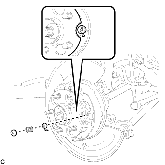
  1. Remove the shoe adjusting hole plug.

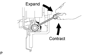
  1. C131914E01
    Turn the shoe adjuster and expand the shoe until the disc locks.

  1. Turn and contract the shoe adjuster until the disc can rotate smoothly.

    Standard:
    Return 8 notches.

  1. Check that there is no brake drag against the shoe.

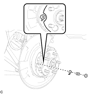
  1. Install the shoe adjusting hole plug.

  1. Turn the adjusting nut until the parking brake pedal travel is corrected to be within the specified range.

    Parking brake pedal travel:
    8 to 10 notches at 300 N (31 kgf, 67 lbf)

  1. Using a wrench or an equivalent tool, hold the adjusting nut and tighten the lock nut.

    Torque:
    7.0 N*m{ 71 kgf*cm , 62 in.*lbf }

  1. Operate the parking brake pedal 3 to 4 times, and check the parking brake pedal travel.

  1. Check that there is no brake drag against the shoe.

  1. Remove the hub nuts.

  1. Install the rear wheel.

    Torque:
    103 N*m{ 1050 kgf*cm , 76 ft.*lbf }

  1. Install the driver side knee airbag assembly (Click here).


22. ADJUST PARKING BRAKE SHOE CLEARANCE AND PARKING BRAKE PEDAL TRAVEL (for RHD)
  1. Remove the driver side knee airbag assembly (Click here).

  1. Completely release the parking brake pedal.

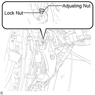
  1. C165692E01
    Loosen the lock nut and adjusting nut to completely release the parking brake cable.

  1. Remove the rear wheel.

  1. Temporarily install the hub nuts.

  1. Remove the shoe adjusting hole plug.

  1. C131914E01
    Turn the shoe adjuster and expand the shoe until the disc locks.

  1. Turn and contract the shoe adjuster until the disc can rotate smoothly.

    Standard:
    Return 8 notches.

  1. Check that there is no brake drag against the shoe.

  1. Install the shoe adjusting hole plug.

  1. Turn the adjusting nut until the parking brake pedal travel is corrected to be within the specified range.

    Parking brake pedal travel:
    8 to 10 notches at 300 N (31 kgf, 67 lbf)

  1. Using a wrench or an equivalent tool, hold the adjusting nut and tighten the lock nut.

    Torque:
    7.0 N*m{ 71 kgf*cm , 62 in.*lbf }

  1. Operate the parking brake pedal 3 to 4 times, and check the parking brake pedal travel.

  1. Check that there is no brake drag against the shoe.

  1. Remove the hub nuts.

  1. Install the rear wheel.

    Torque:
    103 N*m{ 1050 kgf*cm , 76 ft.*lbf }

  1. Install the driver side knee airbag assembly (Click here).


23. INSPECT BRAKE WARNING LIGHT
  1. When operating the parking brake pedal, check that the brake warning light illuminates.

    Standard:
    The brake warning light always illuminates at the first click.


24. INSTALL REAR WHEEL

Torque:
103 N*m{ 1050 kgf*cm , 76 ft.*lbf }

← INSTALLATION (Aug 2008 – Jun 2010)COMPONENTS (from May 2007) →