2007-2013 Highlander Kluger · Service Manual BRAKE

INSTALLATION

Removal / installation · Vehicles built from Jul 2010

Versions by build date: May 2007 – Jul 2008 Aug 2008 – Jun 2010 from Jul 2010


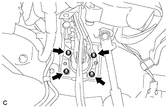
1. INSTALL BRAKE PEDAL SUPPORT SUB-ASSEMBLY (for LHD)

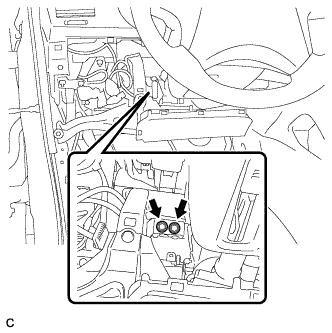
  1. C165374
    Install the brake pedal support sub-assembly with the 4 nuts.

    Torque:
    13 N*m{ 132 kgf*cm , 10 ft.*lbf }

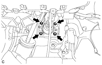
  1. C165373
    Install the brake pedal support sub-assembly to the instrument panel reinforcement with the 2 bolts.

    Torque:
    35 N*m{ 357 kgf*cm , 26 ft.*lbf }

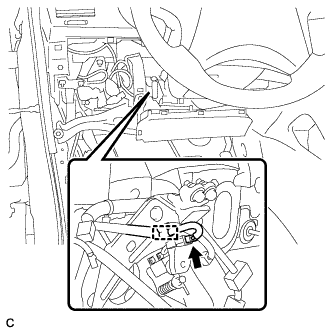
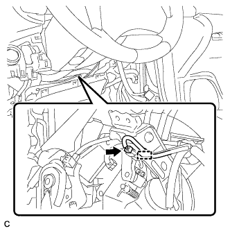
  1. C165371
    Connect the brake pedal load sensing switch connector and engage the clamp.


2. INSTALL BRAKE PEDAL SUPPORT SUB-ASSEMBLY (for RHD)

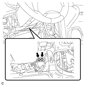
  1. C165376
    Install the brake pedal support sub-assembly with the 4 nuts.

    Torque:
    13 N*m{ 132 kgf*cm , 10 ft.*lbf }

  1. C165375
    Install the brake pedal support sub-assembly to the instrument panel reinforcement with the 2 bolts.

    Torque:
    35 N*m{ 357 kgf*cm , 26 ft.*lbf }

  1. C165372
    Connect the brake pedal load sensing switch connector and engage the clamp.


3. CONNECT BRAKE MASTER CYLINDER PUSH ROD CLEVIS

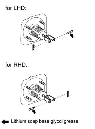
  1. C166415E01
    Apply lithium soap base glycol grease to the push rod pin.

  1. Connect the brake master cylinder push rod clevis to the brake pedal with the push rod pin, and install a new clip as shown in the illustration.


4. INSTALL BRAKE PEDAL RETURN SPRING

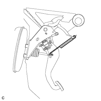
  1. C165369
    Install the brake pedal return spring between the instrument panel reinforcement and brake master cylinder push rod clevis.


5. INSTALL STOP LIGHT SWITCH ASSEMBLY

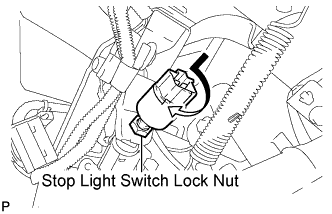
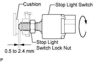
  1. E150075E01
    Temporarily install the stop light switch assembly with the stop light switch lock nut.

  1. E150611E01
    Turn the stop light switch assembly so that the clearance between the nut end and stop light switch cushion is between 0.5 to 2.4 mm (0.020 to 0.095 in.).

  1. Tighten the stop light switch lock nut.

    Torque:
    17 N*m{ 173 kgf*cm , 12 ft.*lbf }

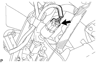
  1. E150073
    Connect the connector.


6. INSPECT AND ADJUST BRAKE PEDAL
(Click here)

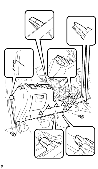
7. INSTALL LOWER INSTRUMENT PANEL FINISH PANEL SUB-ASSEMBLY (for Manual Air Conditioning System)

  1. B168371
    Connect the hood lock control cable assembly.

  1. Connect each connector.

  1. Engage the 3 claws and 10 clips.

  1. Install the lower instrument panel finish panel sub-assembly with the 2 bolts <B>.


8. INSTALL LOWER INSTRUMENT PANEL FINISH PANEL SUB-ASSEMBLY (for Automatic Air Conditioning System)

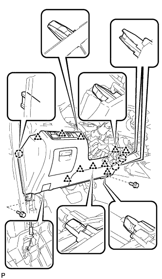
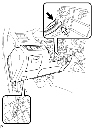
  1. B173009
    Connect the hood lock control cable assembly.

  1. Connect each connector and the aspirator duct.

  1. B173021
    Engage the 3 claws and 10 clips.

  1. Install the lower instrument panel finish panel sub-assembly with the 2 bolts <B>.


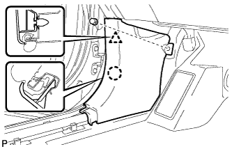
9. INSTALL COWL SIDE TRIM SUB-ASSEMBLY LH

  1. B173227
    Engage the claw and clip, install the cowl side trim sub-assembly LH.

  1. Install the clip.


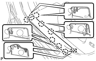
10. INSTALL FRONT DOOR SCUFF PLATE LH

  1. B173224
    Engage the guide and 8 claws, and install the front door scuff plate LH.

← INSTALLATION (Aug 2008 – Jun 2010)COMPONENTS (from May 2007) →