2007-2013 Highlander Kluger · Service Manual BODY

REMOVAL

Removal / installation · Vehicles built from Jul 2010

Versions by build date: May 2007 – Jul 2008 Aug 2008 – Jun 2010 from Jul 2010


1. DISCONNECT BATTERY NEGATIVE TERMINAL

2. REMOVE FRONT DOOR LOWER FRAME BRACKET GARNISH (for Front Door)

  1. B172931
    Disengage the claw and clip, and remove the front door lower frame bracket garnish.


3. REMOVE FRONT DOOR INSIDE HANDLE BEZEL PLUG (for Front Door)

  1. B172920E01
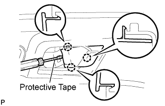
    Using a screwdriver with the tip wrapped with protective tape, disengage the 3 claws, and remove the front door inside handle bezel plug.


4. REMOVE FRONT ARMREST UPPER BASE PANEL (for Front Door)

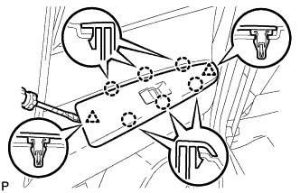
  1. B172922E01
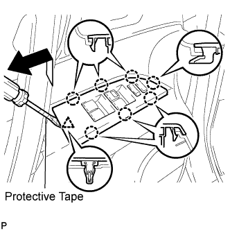
    Using a screwdriver with the tip wrapped with protective tape, disengage the 7 claws and clip, and remove the front armrest upper base panel.

  1. Disconnect the connector.


5. REMOVE ASSIST GRIP COVER (for Front Door)

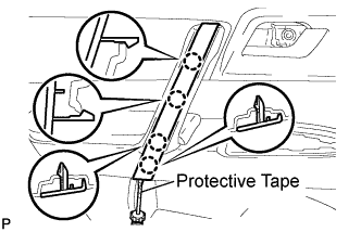
  1. B174183E01
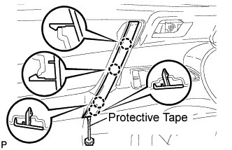
    Using a screwdriver with the tip wrapped with protective tape, disengage the 4 claws and remove the assist grip cover.


6. REMOVE COURTESY LIGHT ASSEMBLY (for Front Door)

  1. B172929E01
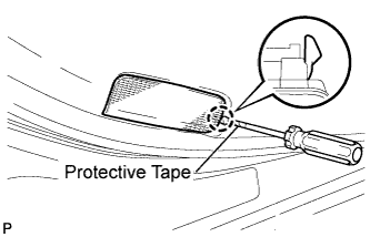
    Using a screwdriver with the tip wrapped with protective tape, disengage the claw and remove the courtesy light assembly.

  1. Disconnect the connector.


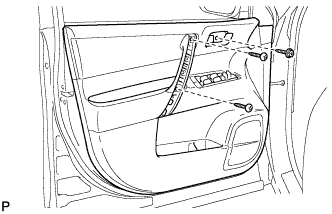
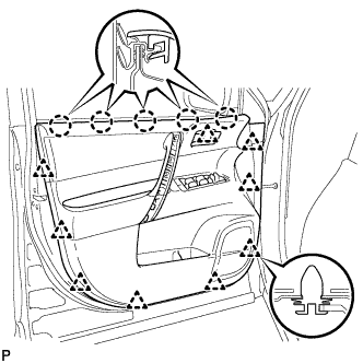
7. REMOVE FRONT DOOR TRIM BOARD SUB-ASSEMBLY (for Front Door)

  1. B172932
    Remove the 3 screws.

  1. B172933
    Using a clip remover, disengage the 9 clips.

  1. Disengage the 5 claws and separate the front door trim board sub-assembly from the front door inner glass weatherstrip.

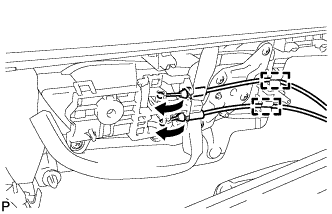
  1. B172934
    Disengage the 2 clamps.

  1. Disconnect the front door lock remote control cable and front door inside locking cable.

  1. Disconnect the connector.


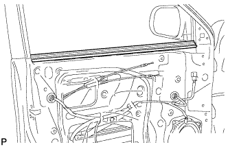
8. REMOVE FRONT DOOR INNER GLASS WEATHERSTRIP (for Front Door)

  1. B172938
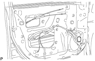
    Remove the front door inner glass weatherstrip from the front door panel.


9. REMOVE FRONT DOOR SERVICE HOLE COVER (for Front Door)

  1. B172939
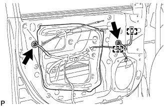
    Disconnect the each connector and 2 clamps, and remove the front door service hole cover.

    HINT:
    Remove the remaining butyl tape on the door side.


10. REMOVE FRONT DOOR GLASS SUB-ASSEMBLY (for Front Door)

  1. B172940
    Remove the hole plug.

  1. Connect the negative battery terminal.

  1. Connect the power window regulator motor connector.

  1. Connect the power window regulator master switch assembly and move the front door glass sub-assembly so that the door glass bolts can be seen.

  1. Disconnect the negative battery terminal and power window regulator master switch assembly.

  1. Disconnect the power window regulator motor connector.

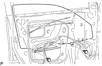
  1. B172941
    Remove the 2 bolts.

    NOTICE:
    After the bolts are removed, do not allow the door to fall.

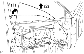
  1. B172942E01
    Remove the front door glass sub-assembly as shown in the illustration.

    NOTICE:
    Do not damage the door glass.


11. REMOVE FRONT DOOR WINDOW REGULATOR SUB-ASSEMBLY (for Front Door)

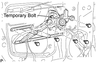
  1. B172943E01
    Loosen the temporary bolt.

    NOTICE:
    Do not remove the temporary bolt. If the temporary bolt is removed, the front door window regulator may fall and cause damage.

  1. Remove the 5 bolts.

  1. Remove the front door window regulator sub-assembly and the front power window regulator motor assembly as a unit.

  1. Remove the temporary bolt from the front door window regulator sub-assembly.


12. REMOVE FRONT POWER WINDOW REGULATOR MOTOR ASSEMBLY (for Front Door)

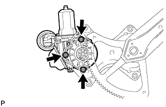
  1. B172944
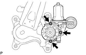
    Using a "TORX" driver (T25), remove the 3 screws and the front power window regulator motor assembly.


13. REMOVE REAR DOOR INSIDE HANDLE BEZEL PLUG (for Rear Door)

  1. B172920E01
    Using a screwdriver with the tip wrapped with protective tape, disengage the 3 claws and remove the rear door inside handle bezel plug.


14. REMOVE REAR DOOR ARMREST UPPER BASE PANEL (for Rear Door)

  1. B172987E01
    Using a screwdriver with the tip wrapped with protective tape, disengage the 6 claws and 2 clips, and remove the rear door armrest upper base panel.

  1. Disconnect the connector.


15. REMOVE DOOR ASSIST GRIP COVER (for Rear Door)

  1. B174184E01
    Using a screwdriver with the tip wrapped with protective tape, disengage the 4 claws and remove the door assist grip cover.


16. REMOVE REAR DOOR TRIM BOARD SUB-ASSEMBLY (for Rear Door)

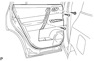
  1. B173155
    Remove the 3 screws.

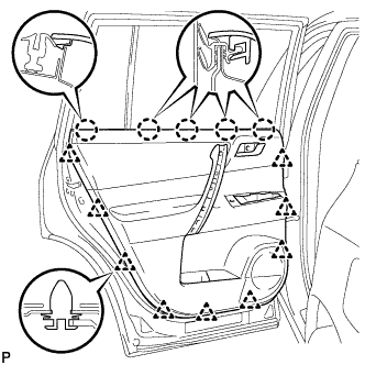
  1. B173156
    Using a clip remover, disengage the 9 clips.

  1. Disengage the 5 claws and separate the rear door trim board sub-assembly from the rear door inner glass weatherstrip.

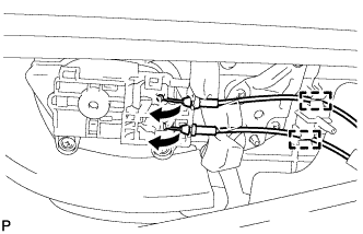
  1. B173157
    Disengage the 2 clamps.

  1. Disconnect the front door lock remote control cable and rear door inside locking cable.


17. REMOVE REAR DOOR INNER GLASS WEATHERSTRIP

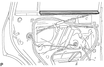
  1. B173160
    Remove the rear door inner glass weatherstrip from the rear door panel.


18. REMOVE REAR DOOR SERVICE HOLE COVER (for Rear Door)

  1. B173161
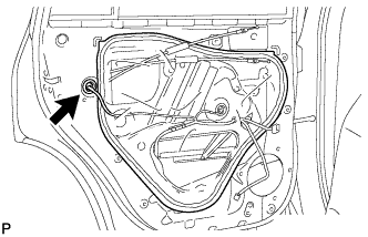
    Disconnect the connector.

  1. Remove the rear door service hole cover.

    HINT:
    Remove the remaining tape on the door.


19. REMOVE REAR DOOR WEATHERSTRIP (for Rear Door)
  1. Remove the upper part of the front door weatherstrip to the extent that allows removal of the rear door window division bar sub-assembly.


20. REMOVE REAR DOOR GLASS RUN (for Rear Door)

  1. B173165
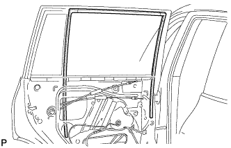
    Remove the rear door glass run.


21. REMOVE REAR DOOR WINDOW DIVISION BAR SUB-ASSEMBLY (for Rear Door)

  1. B173164
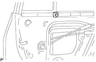
    Remove the rear door vent seal.

  1. B173167
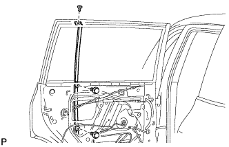
    Remove the 2 bolts, screw, and the rear door window division bar sub-assembly.


22. REMOVE REAR DOOR QUARTER WINDOW GLASS (for Rear Door)

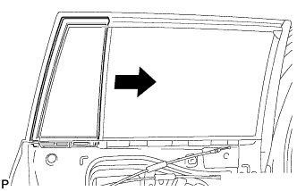
  1. B173168
    Remove the rear door quarter window glass and the rear door quarter window weatherstrip as a unit as shown in the illustration.

  1. Remove the rear door quarter window glass from the rear door quarter window weatherstrip.


23. REMOVE REAR DOOR GLASS SUB-ASSEMBLY (for Rear Door)

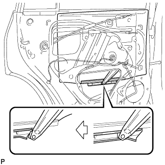
  1. B173170
    Remove the rear door glass sub-assembly from the rear door window regulator sub-assembly as shown in the illustration.

    NOTICE:
    Do not damage the door glass.


24. REMOVE REAR DOOR WINDOW REGULATOR SUB-ASSEMBLY (for Rear Door)

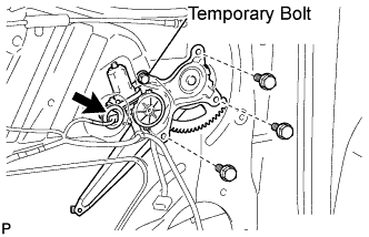
  1. B173172E01
    Disconnect the connector.

  1. Loosen the temporary bolt.

    NOTICE:
    Do not remove the temporary bolt. If the temporary bolt is removed, the rear door window regulator may fall and cause damage.

  1. Remove the 3 bolts.

  1. Remove the rear door window regulator sub-assembly and the rear power window regulator motor assembly as a unit.

  1. Remove the temporary bolt from the rear door window regulator sub-assembly.


25. REMOVE REAR POWER WINDOW REGULATOR MOTOR ASSEMBLY (for Rear Door)

  1. B173173
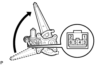
    Connect the positive (+) lead of the battery to terminal 2, and the negative (-) lead to terminal 1 of the rear power window regulator motor assembly to move the lift arm to the position shown in the illustration.

  1. B173175
    Using a "TORX" driver (T25), remove the 3 screws and the rear power window regulator motor assembly.

← REMOVAL (Aug 2008 – Jun 2010)INSPECTION (from May 2007) →