Sliding Roof does not Move by Operating Sliding Roof Control Switch
Circuit diagnosis · Vehicles built Aug 2008 – Jun 2010
Versions by build date: May 2007 – Jul 2008 Aug 2008 – Jun 2010 from Jul 2010
DESCRIPTION
The sliding roof system uses a LIN communication protocol on the multiplex communication system. Inspect the communication system by following HOW TO PROCEED WITH TROUBLESHOOTING (Click here) to ensure that there are no problems with the multiplex communication system before troubleshooting the sliding roof system. The sliding roof system prohibits the AUTO UP/DOWN function if the jam protection function malfunctions. Check that there are no DTCs output before troubleshooting the sliding roof system. If any sliding roof system DTCs are output, perform troubleshooting on the output DTCs first.WIRING DIAGRAM
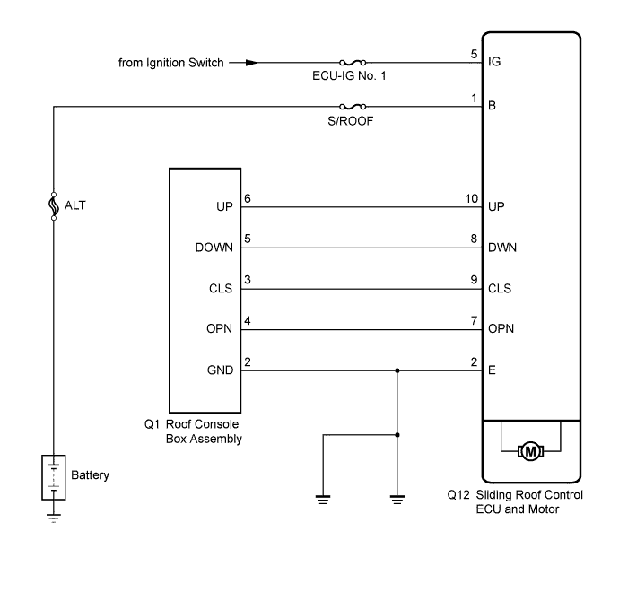

INSPECTION PROCEDURE
| 1. INSPECT FUSE (S/ROOF, ECU-IG NO. 1) |

Remove the S/ROOF and ECU-IG No. 1 fuses from the instrument panel junction block.
Measure the resistance of the fuses.
- Standard resistance:
- Below 1 Ω
|
|
||||

| OK | |
 |
| 2. CHECK WIRE HARNESS (SLIDING ROOF CONTROL ECU - BATTERY AND BODY GROUND) |
Disconnect the Q12 connector.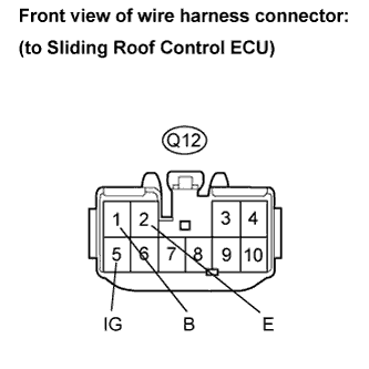
Measure the voltage and resistance according to the value(s) in the table below.
- Standard voltage:
Tester Connection
Condition
Specified Condition
Q12-1 (B) - Body ground
Always
10 to 14 V
Q12-5 (IG) - Body ground
Ignition switch on (IG)
10 to 14 V
Q12-5 (IG) - Body ground
Ignition switch off
Below 1 V
- Standard resistance:
Tester Connection
Condition
Specified Condition
Q12-2 (E) - Body ground
Always
Below 1 Ω
|
|
||||
| OK | |
|
| 3. PERFORM ACTIVE TEST BY INTELLIGENT TESTER (SLIDING ROOF OPERATION) |
Select the ACTIVE TEST, use the intelligent tester to generate a control command, and then check that the sliding roof slides open/close and tilts up/down (Click here).
SLIDE ROOF: Tester Display
Test Part
Control Range
Diagnostic Note
Slide Roof
(Slide Roof)
Operate sliding roof SLIDE CLOSE/TILT UP
CLOSE/UP: Sliding roof SLIDE CLOSE or TILT UP operation occurs.
OFF: Sliding roof is not operating.
-
Slide Roof
(Slide Roof)
Operate sliding roof SLIDE OPEN/TILT DOWN
OPN/DWN: Sliding roof SLIDE OPEN or TILT DOWN operation occurs.
OFF: Sliding roof is not operating.
-
- OK:
- Sliding roof operates normally.
|
|
||||
| OK | |
|
| 4. READ VALUE USING INTELLIGENT TESTER (SLIDING ROOF CONTROL ECU) |
Use the DATA LIST to check if the sliding roof switch assembly is functioning properly (Click here).
SLIDE ROOF: Tester Display
Measurement Item/Range
Normal Condition
Diagnostic Note
Hall IC1 Pulse
(Hall IC1 Pulse)
Sliding roof operation signal/LO or HI
LO: Sliding roof motor is not operating.
HI: Sliding roof motor is operating.
-
Hall IC1 Status
(Hall IC1 Status)
Sliding roof operation signal/NORMAL or LOCK
NORMAL: Sliding roof motor is operating.
LOCK: Sliding roof motor is not operating.
-
Hall IC2 Pulse
(Hall IC2 Pulse)
Sliding roof operation signal/LO or HI
LO: Sliding roof motor is not operating.
HI: Sliding roof motor is operating.
-
Hall IC2 Status
(Hall IC2 Status)
Sliding roof operation signal/NORMAL or LOCK
NORMAL: Sliding roof motor is operating.
LOCK: Sliding roof motor is not operating.
-
|
|
||||
| OK | |
|
| 5. READ VALUE USING INTELLIGENT TESTER (SLIDING ROOF SWITCH ASSEMBLY) |
Use the DATA LIST to check if the sliding roof switch assembly is functioning properly (Click here).
SLIDE ROOF: Tester Display
Measurement Item/Range
Normal Condition
Diagnostic Note
Open SW
(Open Switch)
Slide switch open signal/ON or OFF
ON: OPEN switch is pressed.
OFF: OPEN switch is not pressed.
-
Close SW
(Close Switch)
Slide switch close signal/ON or OFF
ON: CLOSE switch is pressed.
OFF: CLOSE switch is not pressed.
-
Up SW
(Up Switch)
Tilt switch up signal/ON or OFF
ON: UP switch is pressed.
OFF: UP switch is not pressed.
-
Down SW
(Down Switch)
Tilt switch down signal/ON or OFF
ON: DOWN switch is pressed.
OFF: DOWN switch is not pressed.
-
- OK:
- The intelligent tester displays as shown in the table according to the operation of each switch.
|
|
||||

| OK | ||
 |
||
| ||
| 6. INSPECT ROOF CONSOLE BOX ASSEMBLY (SLIDING ROOF SWITCH ASSEMBLY) |
Remove the roof console box assembly.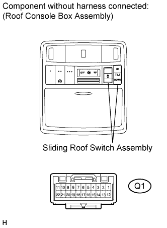
Measure the resistance according to the value(s) in the table below.
- Standard resistance:
Tester Connection
Condition
Specified Condition
Q1-3 (CLS) - Q1-2 (GND)
CLOSE
Below 100 Ω
Q1-4 (OPN) - Q1-2 (GND)
OPEN
Below 100 Ω
Q1-5 (DOWN) - Q1-2 (GND)
DOWN
Below 100 Ω
Q1-6 (UP) - Q1-2 (GND)
UP
Below 100 Ω
Q1-3 (CLS) - Q1-2 (GND)
OPEN
1 kΩ or higher
Q1-4 (OPN) - Q1-2 (GND)
CLOSE
1 kΩ or higher
Q1-5 (DOWN) - Q1-2 (GND)
UP
1 kΩ or higher
Q1-6 (UP) - Q1-2 (GND)
DOWN
1 kΩ or higher
|
|
||||
| OK | |
|
| 7. CHECK WIRE HARNESS (SLIDING ROOF CONTROL ECU - ROOF CONSOLE BOX ASSEMBLY) |
Remove the Q12 and Q1 connectors.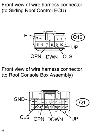
Measure the resistance according to the value(s) in the table below.
- Standard resistance:
Tester Connection
Condition
Specified Condition
Q12-2 (E) - Q1-2 (GND)
Always
Below 1 Ω
Q12-7 (OPN) - Q1-4 (OPN)
Always
Below 1 Ω
Q12-8 (DWN) - Q1-5 (DOWN)
Always
Below 1 Ω
Q12-9 (CLS) - Q1-3 (CLS)
Always
Below 1 Ω
Q12-10 (UP) - Q1-6 (UP)
Always
Below 1 Ω
Q1-3 (CLS) - Body ground
Always
10 kΩ or higher
Q1-4 (OPN) - Body ground
Always
10 kΩ or higher
Q1-2 (GND) - Body ground
Always
Below 1 Ω
Q1-5 (DOWN) - Body ground
Always
10 kΩ or higher
Q1-6 (UP) - Body ground
Always
10 kΩ or higher
|
|
||||
| OK | ||
|
||
| ||