REAR LOWER ARM (for 4WD) > INSTALLATION |
| 1. TEMPORARILY INSTALL REAR NO. 1 SUSPENSION ARM ASSEMBLY LH (for LH Side) |
![]() |
Temporarily install the rear No. 1 suspension arm assembly LH to the rear suspension member sub-assembly with the bolt and the nut.
![]() |
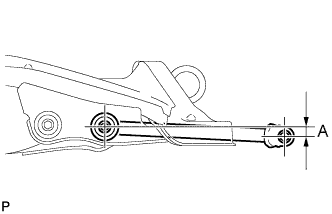
Set the rear No. 1 suspension arm LH in the position shown in the illustration.
Fully tighten the bolt.
| 2. INSTALL REAR SUSPENSION MEMBER (for LH Side) |
![]() |
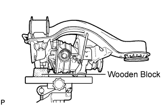
Support the rear suspension member with a jack using a wooden block.
![]() |
Raise the rear suspension member with a jack.
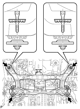
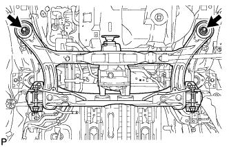
Temporarily install the rear suspension member, 2 rear upper suspension member stoppers, and 2 rear lower suspension member stopper retainers with the 4 nuts and 2 bolts.
![]() |
Fully tighten the 2 nuts.
![]() |
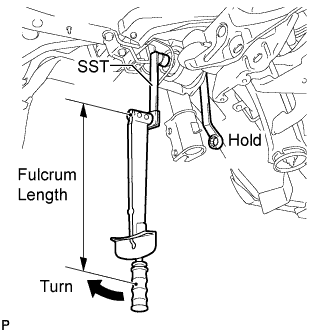
Using SST and a socket wrench (19 mm), fully tighten the nut (LH side).
![]() |
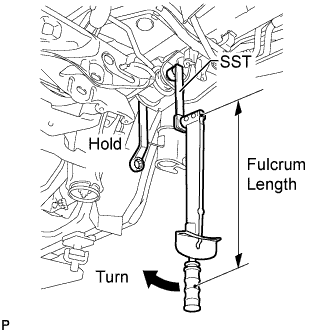
Using SST and a socket wrench (19 mm), fully tighten the nut (RH side).
| 3. INSTALL REAR DRIVE SHAFT SNAP RING LH (for LH Side) |
Install a new rear drive shaft snap ring.
| 4. INSTALL REAR DRIVE SHAFT ASSEMBLY LH (for LH Side) |
![]() |
Align the shaft splines and install the rear drive shaft assembly with a brass bar and hammer.
| 5. INSTALL REAR DRIVE SHAFT SNAP RING RH (for LH Side) |
| 6. INSTALL REAR DRIVE SHAFT ASSEMBLY RH (for LH Side) |
| 7. INSTALL REAR DIFFERENTIAL DRAIN PLUG (for LH Side) |
![]() |
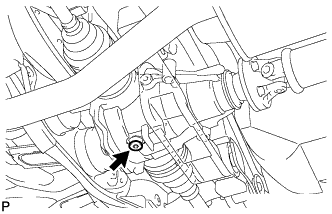
Using a hexagon wrench (10 mm), install the filler plug with a new gasket.
| 8. ADD DIFFERENTIAL OIL (for LH Side) |
Fill the rear differential carrier assembly with hypoid gear oil.
| 9. INSPECT DIFFERENTIAL OIL (for LH Side) |
Stop the vehicle on a level place.
Remove the differential filler plug and gasket.
![]() |
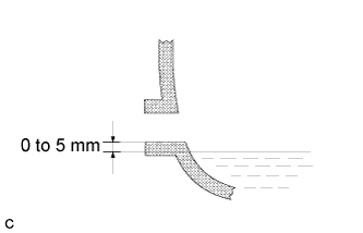
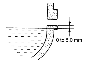
Check that the oil surface is within 5 mm (0.20 in.) of the lowest position of the inner surface of the differential filler plug opening.
Check for oil leakage when the oil level is low.
Install the differential filler plug and a new gasket.
| 10. INSTALL REAR DIFFERENTIAL FILLER PLUG (for LH Side) |
![]() |
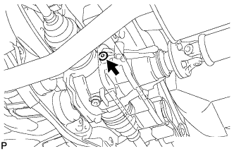
Using a hexagon wrench (10 mm), install the filler plug with a new gasket.
| 11. INSTALL REAR AXLE CARRIER SUB-ASSEMBLY LH (for LH Side) |
![]() |
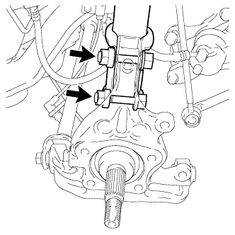
Temporarily install the rear axle carrier sub-assembly LH with the bolt and the nut.
![]() |
Install the rear axle carrier sub-assembly LH with the 2 bolts and the 2 nuts.
| 12. INSTALL REAR AXLE CARRIER SUB-ASSEMBLY RH (for LH Side) |
![]() |
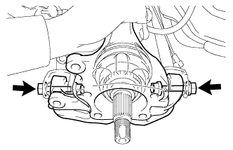
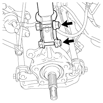
Temporarily install the the rear axle carrier sub-assembly LH with the 2 bolts and the 2 nuts.
![]() |
Install the rear axle carrier sub-assembly LH with the 2 bolts and the 2 nuts.
| 13. TEMPORARILY INSTALL REAR NO. 1 SUSPENSION ARM ASSEMBLY RH (for RH Side) |
![]() |
Temporarily install the rear No. 1 suspension arm assembly RH to the rear suspension member sub-assembly with the bolt and the nut.
Temporarily install the rear No. 1 suspension arm assembly RH to the rear axle carrier sub-assembly RH with the bolt and the nut.
| 14. TEMPORARILY INSTALL REAR STRUT ROD ASSEMBLY LH (for LH Side) |
![]() |
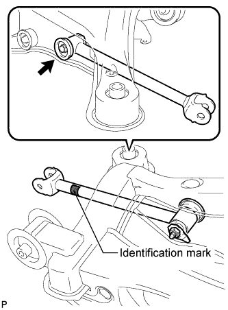
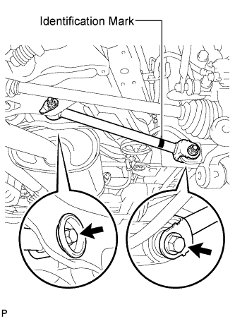
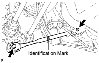
Check that the identification mark of the rear strut rod assembly is positioned on the inner side of the vehicle.
Temporarily install the rear strut rod assembly with the 2 bolts and the 2 nuts.
| 15. TEMPORARILY INSTALL REAR STRUT ROD ASSEMBLY RH |
| 16. TEMPORARILY INSTALL REAR NO. 2 SUSPENSION ARM ASSEMBLY LH (for LH Side) |
![]() |
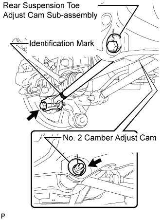
Temporarily install the rear No. 2 suspension arm assembly LH to the rear suspension member sub-assembly with the rear suspension toe adjust cam sub-assembly, the No. 2 camber adjust cam and the nut.
Temporarily install the rear No. 2 suspension arm assembly LH to the rear axle carrier sub-assembly LH with the bolt and the nut.
| 17. TEMPORARILY INSTALL REAR NO. 2 SUSPENSION ARM ASSEMBLY RH (for RH Side) |
| 18. INSTALL REAR AXLE HUB AND BEARING ASSEMBLY LH (for LH Side) |
![]() |
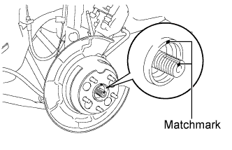
Align the matchmarks on the drive shaft and rear axle hub.
![]() |
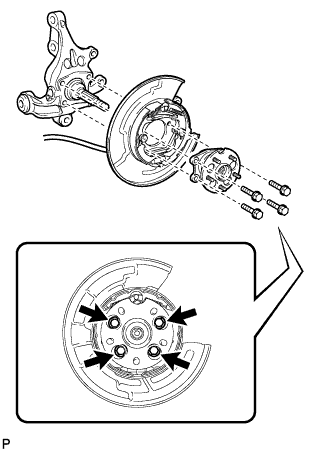
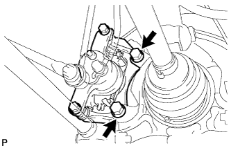
Install the parking brake assembly and the rear axle hub and bearing assembly with the 4 bolts.
| 19. INSTALL REAR AXLE HUB AND BEARING ASSEMBLY RH (for LH Side) |
| 20. INSTALL REAR DISC (for LH Side) |
Install the rear disc to the rear axle hub and bearing assembly LH .
Install the rear disc to the rear axle hub and bearing assembly RH .
| 21. INSTALL REAR DISC BRAKE CALIPER ASSEMBLY LH (for LH Side) |
![]() |
Install the rear disc brake caliper assembly with the 2 bolts.
| 22. INSTALL REAR DISC BRAKE CALIPER ASSEMBLY RH (for LH Side) |
| 23. TEMPORARILY INSTALL REAR AXLE SHAFT NUT LH (for LH Side) |
![]() |
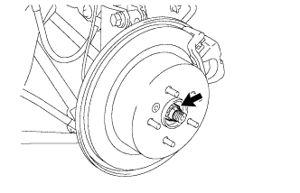
Clean the threaded parts on the rear drive shaft assembly and rear axle shaft nut using a non-residue solvent.
While applying the brakes, temporarily install a new rear axle shaft nut.
| 24. TEMPORARILY INSTALL REAR AXLE SHAFT NUT RH (for LH Side) |
| 25. INSTALL REAR SPEED SENSOR LH (for LH Side) |
![]() |
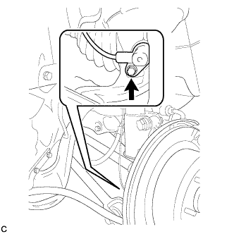
Install the rear speed sensor to the rear axle carrier sub-assembly with the bolt .
| 26. INSTALL REAR SPEED SENSOR RH (for LH Side) |
| 27. STABILIZE SUSPENSION |
![]() |
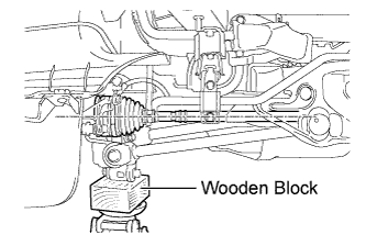
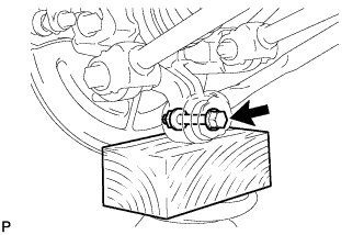
Jack up the rear axle carrier sub-assembly, placing a wooden block underneath to avoid damage. Apply load to the suspension so that the rear drive shaft assembly is positioned horizontally.
| 28. FULLY TIGHTEN REAR NO. 1 SUSPENSION ARM ASSEMBLY LH (for LH Side) |
![]() |
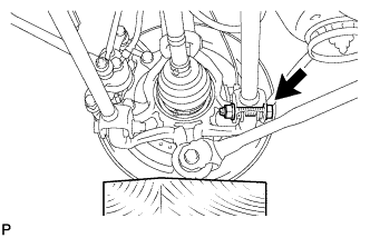
Fully tighten the rear No. 1 suspension arm assembly with the bolt and nut.
| 29. FULLY TIGHTEN REAR NO. 1 SUSPENSION ARM ASSEMBLY RH (for LH Side) |
Fully tighten the rear No. 1 suspension arm assembly RH.
| 30. FULLY TIGHTEN REAR NO. 1 SUSPENSION ARM ASSEMBLY RH (for RH Side) |
![]() |
Fully tighten the 2 bolts.
| 31. FULLY TIGHTEN REAR NO. 2 SUSPENSION ARM ASSEMBLY LH (for LH Side) |
![]() |
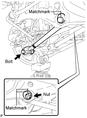
Align the matchmarks on the adjust cams and rear suspension member sub-assembly.
Fully tighten the nut.
Fully tighten the bolt.
| 32. FULLY TIGHTEN REAR NO. 2 SUSPENSION ARM ASSEMBLY RH (for RH Side) |
| 33. FULLY TIGHTEN REAR NO. 2 SUSPENSION ARM ASSEMBLY RH (for LH Side) |
Fully tighten the rear No. 2 suspension arm assembly RH.
| 34. FULLY TIGHTEN REAR STRUT ROD ASSEMBLY LH (for LH Side) |
![]() |
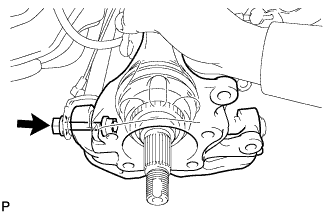
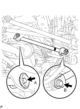
Fully tighten the bolt.
![]() |
Fully tighten the bolt.
| 35. FULLY TIGHTEN REAR STRUT ROD ASSEMBLY RH |
| 36. INSTALL NO. 3 PARKING BRAKE CABLE ASSEMBLY (for LH Side) |
![]() |
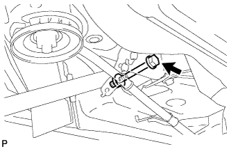
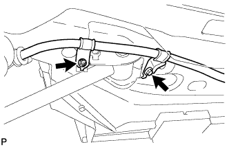
Install the No. 3 parking brake cable assembly with the bolt and the nut.
| 37. INSTALL NO. 2 PARKING BRAKE CABLE ASSEMBLY |
| 38. SEPARATE REAR DISC BRAKE CALIPER ASSEMBLY LH (for LH Side) |
![]() |
Remove the 2 bolts and separate the rear disc brake caliper assembly.
| 39. SEPARATE REAR DISC BRAKE CALIPER ASSEMBLY RH (for LH Side) |
| 40. REMOVE REAR DISC (for LH Side) |
Remove the rear disc from the rear axle hub and bearing assembly LH .
Remove the rear disc from the rear axle hub and bearing assembly RH .
| 41. INSPECT REAR AXLE HUB BEARING LOOSENESS (for LH Side) |
Inspect the rear axle hub bearing looseness .
| 42. INSPECT REAR AXLE HUB RUNOUT (for LH Side) |
Inspect the rear axle hub bearing runout .
| 43. INSTALL REAR DISC (for LH Side) |
Install the rear disc to the rear axle hub and bearing assembly LH .
Install the rear disc to the rear axle hub and bearing assembly RH .
| 44. INSTALL REAR DISC BRAKE CALIPER ASSEMBLY LH (for LH Side) |
![]() |
Install the rear disc brake caliper assembly with the 2 bolts.
| 45. INSTALL REAR DISC BRAKE CALIPER ASSEMBLY RH (for LH Side) |
| 46. INSTALL REAR AXLE SHAFT NUT LH (for LH Side) |
![]() |
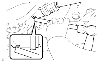
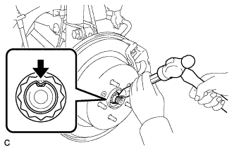
Using a chisel and a hammer, stake the rear axle shaft nut.
| 47. INSTALL REAR AXLE SHAFT NUT RH (for LH Side) |
| 48. TEMPORARILY TIGHTEN PROPELLER WITH CENTER BEARING SHAFT ASSEMBLY (for LH Side) |
![]() |
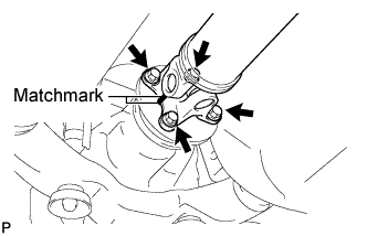
Align the matchmarks on the propeller shaft flange and differential companion flange, and connect the shaft with the 4 bolts, 4 washers and 4 nuts.
![]() |
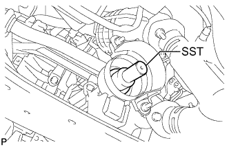
Remove SST from the transaxle.
Insert the yoke into the transaxle.
![]() |
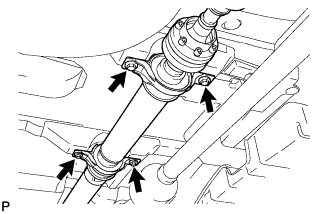
Install the 4 adjusting shims and propeller shaft with center bearing, and temporarily tighten the 4 bolts.
![]() |
Tighten the 4 bolts.
| 49. FULLY TIGHTEN PROPELLER WITH CENTER BEARING SHAFT ASSEMBLY (for LH Side) |
![]() |
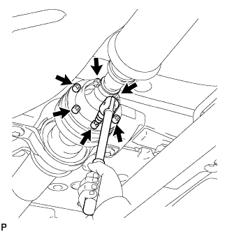
Remove the piece of cloth from the joint.
Using a hexagon wrench (6 mm), tighten the 6 bolts.
![]() |
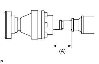
With the vehicle unloaded, adjust the dimension between the rear side of the cover and shaft as shown in the illustration.
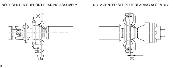
Under the same condition as above, adjust the front and rear dimensions between the edge surface of the center support bearing and the edge surface of the cushion respectively as shown, and then tighten the bolts.

Check that the center line of the bracket is at the right angle in the shaft axial direction.
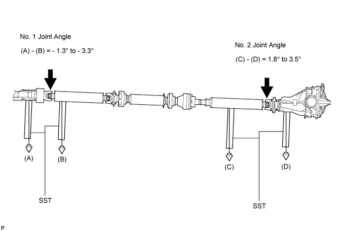
If any vibration or noise occurs, perform joint angle check as follows and replace the adjusting shim with a proper one.
Turn the propeller shaft several times by hand to stabilize the center support bearings.
Using a jack, raise and lower the differential to stabilize the differential mounting cushion.
Remove the transfer dynamic damper.
Using SST, measure the transfer installation angle (A) and front propeller shaft installation angle (B).
Using SST, measure the rear propeller shaft installation angle (C) and rear differential shaft installation angle (D).

| Thickness mm (in.) | Thickness mm (in.) |
| 3.2 (0.126) | 11.0 (0.433) |
| 4.5 (0.177) | 13.5 (0.531) |
| 6.5 (0.256) | 15.5 (0.610) |
| 9.0 (0.354) | 17.5 (0.689) |
Install the transfer dynamic damper.
| 50. INSPECT AND ADJUST TRANSFER OIL (for LH Side) |
![]() |
Remove the No. 1 transfer case plug and gasket.
Check the oil level is within 0 to 5 mm (0 to 0.20 in.) below the lowest end of the hole for the No. 1 transfer case plug.
When the oil level is too low, check for oil leakage.
Tighten the No. 1 transfer case plug with a new gasket.
| 51. INSTALL CENTER EXHAUST PIPE ASSEMBLY |
![]() |
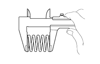
Using vernier calipers, measure the free length of the compression spring.
| Minimum | 41.5 mm (1.63 in.) |
![]() |
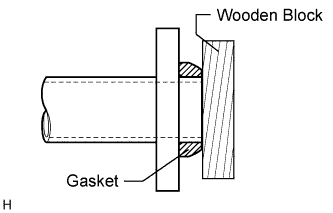
Using a plastic-faced hammer and wooden block, tap in a new gasket until its surface is flush with the front No. 3 exhaust pipe sub-assembly.
Connect the 3 exhaust pipe supports, and install the center exhaust pipe assembly.
![]() |
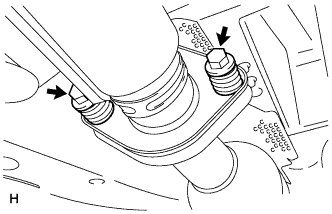
Install the 2 compression springs and 2 bolts.
| 52. INSTALL TAIL EXHAUST PIPE ASSEMBLY |
![]() |
Using vernier calipers, measure the free length of the compression spring.
| Minimum | 40.5 mm (1.59 in.) |
![]() |
Using a plastic-faced hammer and wooden block, tap in a new gasket until its surface is flush with the center exhaust pipe assembly.
Connect the exhaust pipe support, and install the tail exhaust pipe assembly.
![]() |
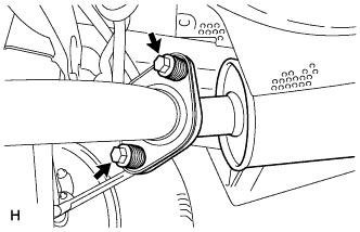
Install the 2 compression springs and 2 bolts.
| 53. INSPECT FOR EXHAUST GAS LEAK |
| 54. INSTALL REAR WHEELS (for LH Side) |
| 55. INSTALL REAR WHEEL (for RH Side) |
| 56. INSPECT AND ADJUST REAR WHEEL ALIGNMENT |
| 57. CHECK FOR REAR SPEED SENSOR SIGNAL (for LH Side) |