REAR WHEEL ALIGNMENT > ADJUSTMENT |
| 1. INSPECT TIRES |
Inspect the tires (Click here).
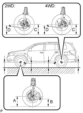
| 2. MEASURE VEHICLE HEIGHT |
Bounce on the vehicle up and down at the corners to stabilize the suspension.
![]() |
Measure the vehicle height.
| Model | Front A - B | Rear C - D |
| 2WD | 118.2 mm (4.65 in.) | 34.9 mm (1.37 in.) |
| 4WD | 118.3 mm (4.66 in.) | 33.8 mm (1.33 in.) |
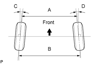
| 3. INSPECT TOE-IN |
![]() |
| Item | Specified Condition |
| Toe-in (2WD) (total) | C + D: 0°10' +/- 0°12' (0.17° +/- 0.2°) B - A: 3.0 +/- 2.0 mm (0.12 +/- 0.08 in.) |
| Toe-in (4WD) (total) | C + D: 0°8' +/- 0°12' (0.14° +/- 0.2°) B - A: 3.0 +/- 2.0 mm (0.12 +/- 0.08 in.) |
| 4. ADJUST TOE-IN (for 2WD) |
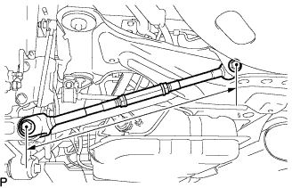
![]() |
Measure the lengths of the right and left rear No. 2 suspension arms.
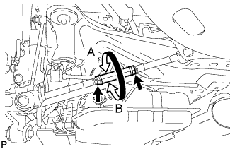
![]() |
Loosen the 2 lock nuts.
If the length difference between the left and right rear No. 2 suspension arm assemblies is not within the specified range, adjust it by following the procedures below.
If the toe-in measurement is greater than the specified range, extend the shorter rear No. 2 suspension arm assembly by rotating the adjusting tube in the direction of arrow B in the illustration.
If the toe-in measurement is less than the specified range, shorten the longer rear No. 2 suspension arm assembly by rotating the adjusting tube in the direction of arrow A in the illustration.
Measure the toe-in.
Turn the right and left adjusting tubes by an equal amount to adjust toe-in.
Tighten the 2 lock nuts.
| 5. ADJUST TOE-IN (for 4WD) |
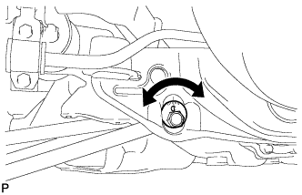
![]() |
Measure the distance between each wheel disc and the center of the toe-adjusting cam, and then confirm that left and right distances are the same.
Loosen the toe-adjust cam set nuts.
Turn the adjust cams by an equal amount to adjust toe-in.
Tighten the toe-adjust cam set nuts.
| 6. INSPECT CAMBER |
| - | 2WD | 4WD | Right-left difference |
| Camber | -1°00' +/- 45' (-1.00° +/- 0.75°) | -0°36' +/- 45' (-0.60° +/- 0.75°) | 45' (0.75°) or less |
| 7. PLACE FRONT WHEELS FACING STRAIGHT AHEAD |
| 8. DISCONNECT CABLE FROM NEGATIVE BATTERY TERMINAL |
| 9. CONNECT CABLE TO NEGATIVE BATTERY TERMINAL |
| 10. PERFORM YAW RATE SENSOR ZERO POINT CALIBRATION |
| 11. CHECK STEERING ANGLE SENSOR ZERO POINT CALIBRATION |