 |
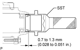
Using SST, install a new transfer RH bearing retainer oil seal to the transfer case at the position as show in the illustration.
- SST
- 09223-46011
- NOTICE:
- Do not install the oil seal obliquely.
- Do not damage the oil seal lip.
BEARING RETAINER OIL SEAL > INSTALLATION |
| 1. INSTALL TRANSFER RH BEARING RETAINER OIL SEAL |
|
Using SST, install a new transfer RH bearing retainer oil seal to the transfer case at the position as show in the illustration.
Apply small amount of MP grease to the oil seal lip.
| 2. INSTALL FRONT DRIVE SHAFT HOLE SNAP RING |
Install a new front drive shaft hole snap ring.
| 3. INSTALL FRONT DRIVE SHAFT ASSEMBLY RH (for 2WD) |
Install the front drive shaft assembly RH.
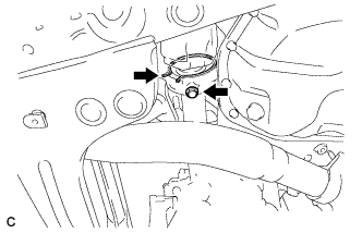 |
Install a new bearing bracket hole snap ring and bolt.
| 4. INSTALL FRONT DRIVE SHAFT ASSEMBLY RH (for 4WD) |
| 5. INSTALL FRONT AXLE ASSEMBLY |
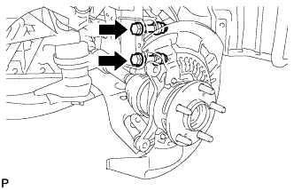 |
Install the front axle assembly to the front shock absorber with the 2 bolts and 2 nuts.
| 6. INSTALL NO. 1 FRONT SUSPENSION LOWER ARM |
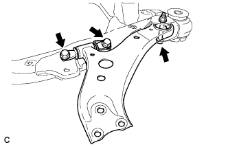 |
Remove the 3 bolts, nut, and the front lower suspension arm from the front frame assembly.
Remove the front lower arm bushing stopper from the front lower suspension arm.
| 7. CONNECT TIE ROD END SUB-ASSEMBLY |
| 8. INSTALL FRRONT SPEED SENSOR |
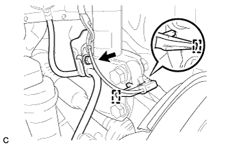 |
Install the front speed sensor and front flexible hose with the bolt.
Install the clamp.
| 9. INSTALL FRONT STABILIZER LINK ASSEMBLY |
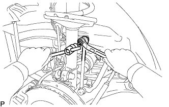 |
Install the front stabilizer link assembly to the front shock absorber with the nut.
| 10. INSTALL FRONT AXLE HUB NUT |
Clean the threaded parts on the drive shaft and axle hub nut using a non-residue solvent.
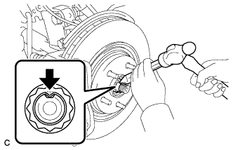 |
Using a socket wrench (30 mm), install a new axle hub nut.
Using a chisel and hammer, stake the front axle hub nut.
| 11. INSTALL FRONT WHEEL |
| 12. ADD AUTOMATIC TRANSAXLE FLUID |
| 13. INSPECT FLUID LEVEL |
Park the vehicle on a level surface and set the parking brake.
 |
With the engine idling and the brake pedal depressed, move the shift lever to all positions from P to S1 and return to the P position.
Take out the dipstick and wipe it clean.
Put the dipstick back all the way.
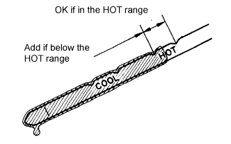
Take out the dipstick again and check that the fluid level is within the HOT range.
If the fluid level is below the HOT range, add new fluid and recheck the fluid level.
If the fluid level exceeds the HOT range, drain the fluid once, add the proper amount of new fluid and recheck the fluid level.
If there are leaks, it is necessary to repair or replace O-rings, FIPGs, oil seals, plugs and/or other parts.
| 14. INSTALL TRANSFER DRAIN PLUG |
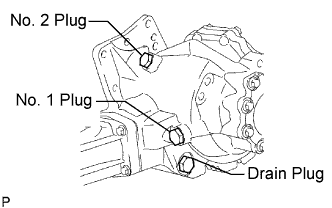 |
Install the transfer drain plug with a new drain gasket.
| 15. INSTALL NO. 1 TRANSFER CASE PLUG |
Add oil up to 0 to 5 mm below the lower side of the plug hole.
Install the No. 1 transfer case plug with a new No. 1 gasket.
| 16. INSPECT EXHAUST GAS LEAK |
| 17. INSTALL NO. 2 ENGINE UNDER COVER |
| 18. INSTALL NO. 1ENGINE UNDER COVER |
| 19. INSTALL ENGINE UNDER COVER ASSEMBLY |
| 20. INSPECT AND ADJUST FRONT WHEEL ALIGNMENT |
| 21. CHECK ABS SPEED SENSOR SIGNAL |