 |
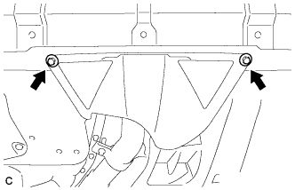
Remove the 2 bolts and engine under cover assembly RR.
DIFFERENTIAL OIL SEAL > REPLACEMENT |
| 1. REMOVE ENGINE UNDER COVER ASSEMBLY |
|
Remove the 2 bolts and engine under cover assembly RR.
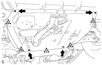 |
Remove the 2 bolts, 2 screws, 5 clips and engine under cover assembly.
| 2. REMOVE NO. 1 ENGINE UNDER COVER |
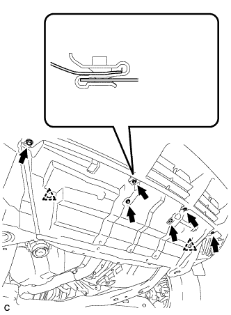 |
Remove the 6 bolts, 2 clips and No. 1 engine under cover.
| 3. REMOVE NO. 2 ENGINE UNDER COVER |
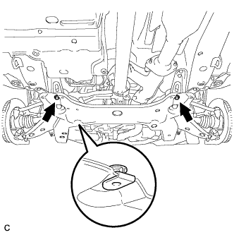 |
Remove the 2 bolts and No. 2 engine under cover.
| 4. DRAIN AUTOMATIC TRANSAXLE FLUID |
Remove the drain plug and gasket, and drain ATF.
Install a new gasket and the drain plug.
| 5. REMOVE FRONT WHEEL |
| 6. REMOVE FRONT AXLE HUB NUT LH |
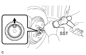 |
Using SST and a hammer, release the staked part of the front axle hub nut.
While applying the brakes, remove the front axle hub nut.
| 7. SEPARATE FRONT STABILIZER LINK ASSEMBLY LH |
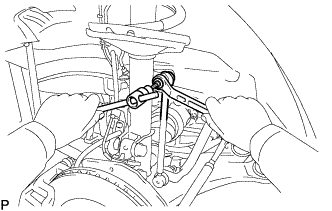 |
Remove the nut and separate the front stabilizer link assembly from the front shock absorber.
| 8. SEPARATE FRONT SPEED SENSOR LH |
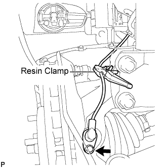 |
Remove the bolt and resin clamp, and separate the front speed sensor.
| 9. SEPARATE TIE ROD ASSEMBLY LH |
Remove the cotter pin and the nut.
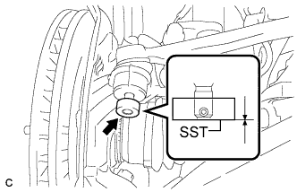 |
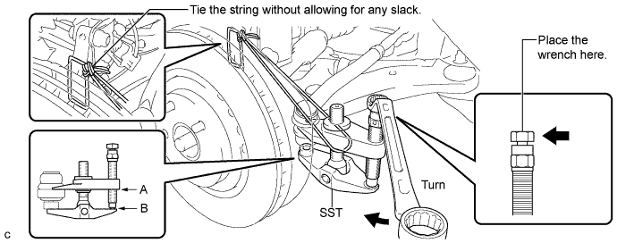
Install SST to the tie rod end.
Using SST, separate the tie rod end from the steering knuckle.
| 10. SEPARATE NO. 1 FRONT SUSPENSION LOWER ARM LH |
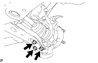 |
Remove the bolt and 2 nuts, and separate the front lower suspension arm from the front lower ball joint.
| 11. SEPARATE FRONT AXLE ASSEMBLY LH |
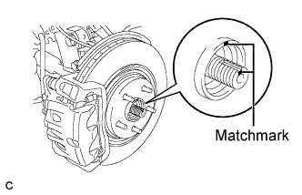 |
Put matchmarks on the front drive shaft assembly and the front axle hub sub-assembly.
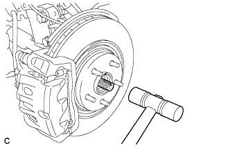 |
Using a plastic hammer, separate the front drive shaft assembly from the front axle assembly.
| 12. REMOVE FRONT DRIVE SHAFT ASSEMBLY LH |
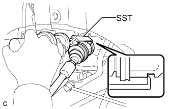 |
Using SST, remove the front drive shaft assembly LH.
| 13. SECURE FRONT AXLE HUB SUB-ASSEMBLY LH |
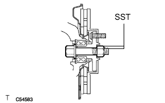 |
Using SST, secure the front axle hub bearing.
| 14. REMOVE DIFFERENTIAL SIDE BEARING RETAINER OIL SEAL |
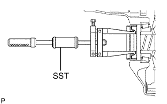 |
Using SST, pull out the oil seal.
| 15. INSTALL DIFFERENTIAL SIDE BEARING RETAINER OIL SEAL |
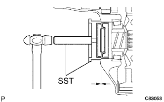 |
Coat the lip of a new oil seal with MP grease.
Using SST and a hammer, install a new oil seal.
| 16. INSTALL FRONT DRIVE SHAFT ASSEMBLY LH |
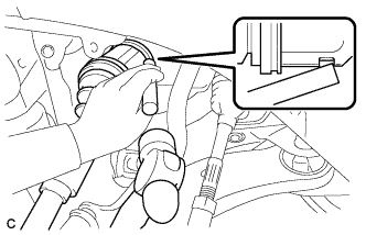 |
Align the shaft splines and install the drive shaft assembly LH with a brass bar and hammer.
| 17. INSTALL FRONT AXLE ASSEMBLY LH |
|
Align the matchmarks and install the front drive shaft assembly to the front axle hub sub-assembly.
| 18. INSTALL NO. 1 FRONT SUSPENSION LOWER ARM LH |
|
Install the front lower suspension arm to the front lower ball joint with the bolt and 2 nuts.
| 19. INSTALL TIE ROD ASSEMBLY LH |
Connect the tie rod assembly LH to the steering knuckle with the nut.
Install a new cotter pin.
| 20. INSTALL FRONT SPEED SENSOR LH |
|
Install the resin clamp and front speed sensor with the bolt.
| 21. INSTALL FRONT STABILIZER LINK ASSEMBLY LH |
|
Install the front stabilizer link assembly to the front shock absorber with the nut.
| 22. INSTALL FRONT AXLE HUB NUT LH |
Clean the threaded parts on the drive shaft and axle hub nut using a non-residue solvent.
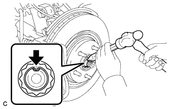 |
Using a socket wrench (30 mm), install a new axle hub nut.
Using a chisel and hammer, stake the front axle hub nut.
| 23. INSTALL FRONT WHEEL |
| 24. ADD AUTOMATIC TRANSAXLE FLUID |
| 25. INSPECT AUTOMATIC TRANSAXLE FLUID |
Park the vehicle on a level surface and set the parking brake.
 |
With the engine idling and the brake pedal depressed, move the shift lever to all positions from P to S1 and return to the P position.
Take out the dipstick and wipe it clean.
Put the dipstick back all the way.
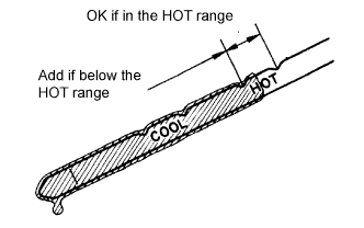
Take out the dipstick again and check that the fluid level is within the HOT range.
If the fluid level is below the HOT range, add new fluid and recheck the fluid level.
If the fluid level exceeds the HOT range, drain the fluid once, add the proper amount of new fluid and recheck the fluid level.
If there are leaks, it is necessary to repair or replace O-rings, FIPGs, oil seals, plugs and/or other parts.
| 26. INSTALL NO. 2 ENGINE UNDER COVER |
|
Install the No. 2 engine under cover with the 2 bolts.
| 27. INSTALL NO. 1 ENGINE UNDER COVER |
|
Install the No. 1 engine under cover with the 6 bolts and 2 clips.
| 28. INSTALL ENGINE UNDER COVER ASSEMBLY |
|
Install the engine under cover assembly with the 4 bolts and 5 clips.
|
Install the engine under cover assembly RR with the 2 bolts.
| 29. INSTALL FRONT WHEEL ALIGNMENT |
| 30. INSTALL ABS SPEED SENSOR SIGNAL |
| 31. REMOVE AUTOMATIC TRANSAXLE ASSEMBLY |
| 32. REMOVE NO. 1 TRANSFER CASE PLUG |
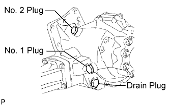 |
Remove the No. 1 transfer case plug.
Remove the No. 1 gasket from the No. 1 transfer case plug.
| 33. REMOVE NO. 2 TRANSFER CASE PLUG |
Remove the No. 2 transfer case plug.
Remove the No. 2 gasket from the No. 2 transfer case plug.
| 34. REMOVE TRANSFER DRAIN PLUG |
Remove the transfer drain plug and bleed the oil.
Remove the drain gasket from the transfer drain plug.
| 35. REMOVE TRANSFER ASSEMBLY |
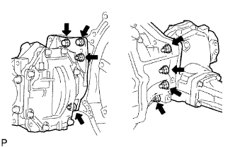 |
Remove the 2 bolts and 6 nuts.
Using a plastic hammer, remove the transfer assembly from the transaxle assembly.
| 36. REMOVE TRANSAXLE HOUSING OIL SEAL |
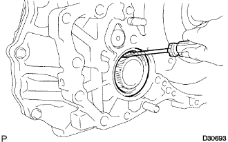 |
Using a screwdriver with vinyl tape wrapped around its tip, remove the oil seal.
| 37. INSTALL TRANSAXLE HOUSING OIL SEAL |
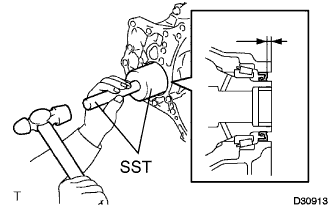 |
Coat the lip of a new oil seal with MP grease.
Using SST and a hammer, install a new oil seal.
| 38. INSTALL TRANSFER ASSEMBLY |
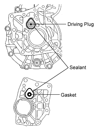 |
Apply sealant 1281 to the transaxle assembly and transfer assembly in a continuous bead of 1.2 mm diameter as shown in the illustration.
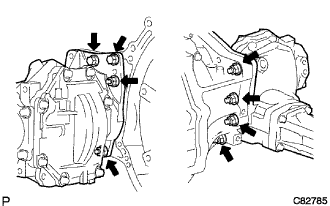 |
Install the transfer assembly to the transaxle assembly with the 2 bolts and 6 nuts.
| 39. INSTALL AUTOMATIC TRANSAXLE ASSEMBLY |