| B |  |
| GO TO DTC CHART (P0A1F-123) (Click here) |
DTC P0AFA-123 Hybrid Battery System Voltage Low |
| DTC No. | DTC Detection Condition | Trouble Area |
| P0AFA-123 | Each battery block voltage becomes less than 2.5 V (open) (1 trip detection) |
|
| Related DTCs | P0AFA-123 |
| Required sensors/components | The wire harness between each battery block and the battery smart unit |
| Frequency of operation | Continuous |
| Duration | TOYOTA's intellectual property |
| MIL operation | Immediately |
| Sequence of operation | None |
| The monitor will run whenever the DTCs listed are not present | TOYOTA's intellectual property |
| Part of battery voltage | Less than 2.5 V |
| All battery voltage | Less than 2.5 V |
| Battery smart unit | No open malfunction |
| 1.CHECK DTC OUTPUT (DTC P0A1F-123 IS OUTPUT) |
Connect the Techstream to the DLC3.
Turn the power switch on (IG).
Select the following menu items: Powertrain / Hybrid Control / Trouble Codes.
Read output DTCs (Click here).
| Result | Proceed to |
| P0A1F-123 is not output. | A |
| P0A1F-123 is also output. | B |
|
| ||||
| A | |
 |
| 2.CHECK CONNECTOR CONNECTION CONDITION (BATTERY SMART UNIT CONNECTOR) |
Remove the battery cover (Click here).
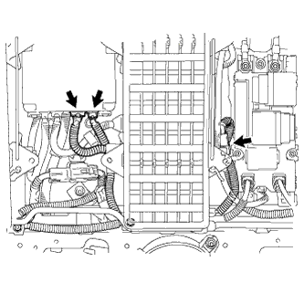 |
Check the connections of the connectors shown in the illustration.
| Specified Condition |
| The connectors are connected securely and there are no contact problems. |
|
| ||||
| OK | |
|
| 3.REPLACE BATTERY SMART UNIT |
Replace the battery smart unit (Click here).
| NEXT | |
|
| 4.CLEAR DTC |
Connect the Techstream to the DLC3.
Turn the power switch on (IG).
Select the following menu items: Powertrain / Hybrid Control / Trouble Codes.
Clear DTCs and freeze frame data (Click here).
| NEXT | |
|
| 5.RECONFIRM DTC OUTPUT |
Connect the Techstream to the DLC3.
Turn the power switch on (IG).
Select the following menu items: Powertrain / Hybrid Control / Trouble Codes.
Read output DTCs.
| Result | Proceed to |
| P0AFA-123 is not output. | A |
| DTC P0AFA-123 is output. | B |
|
| ||||
| A | ||
 | ||
| ||