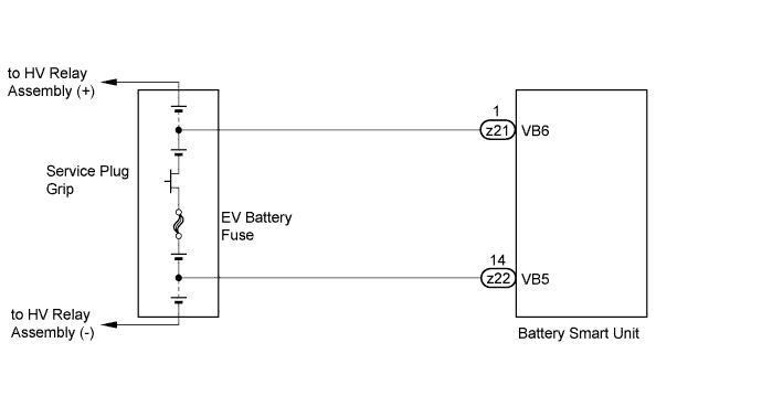
DTC P0A95-123 High Voltage Fuse |
| DTC No. | DTC Detection Condition | Trouble Area |
| P0A95-123 | Voltage between VB5 and VB6 terminals is below the standard despite the interlock switch being engaged (1 trip detection) |
|
| 1.CHECK DTC OUTPUT (DTC P0A1F IS OUTPUT) |
Connect the Techstream to the DLC3.
Turn the power switch on (IG).
Select the following menu items: Powertrain / Hybrid Control / Trouble Codes.
Read output DTCs (Click here).
| Result | Proceed to |
| P0A1F-123 is not output. | A |
| P0A1F-123 is also output. | B |
|
| ||||
| A | |
 |
| 2.CHECK EV BATTERY FUSE (HIGH VOLTAGE FUSE) |
Turn the power switch off.
Remove the service plug grip (Click here).
Remove the fuse block cover (Click here).
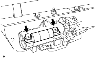 |
Measure the resistance between the EV battery fuse terminals.
| Tester Connection | Standard Resistance |
| EV battery fuse | Below 1 Ω |
|
| ||||
| OK | |
|
| 3.INSPECT EV BATTERY PLUG |
Remove the battery cover (Click here).
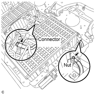 |
Remove the nut shown in the illustration.
Disconnect the connector shown in the illustration.
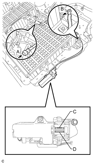 |
Measure the resistance according to the value(s) in the table below.
| Tester Connection | Switch Condition | Specified Condition |
| A - C | Power switch off | Below 1 Ω |
| B - D | Power switch off | Below 1 Ω |
|
| ||||
| OK | |
|
| 4.CHECK MAIN BATTERY CABLE |
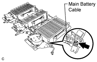 |
Remove the nut shown in the illustration.
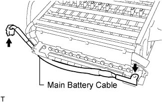 |
Measure the resistance between the main battery cable terminals.
| Tester Connection | Standard Resistance |
| Main battery cable | Below 1 Ω |
|
| ||||
| OK | ||
 | ||
| ||
