 |
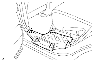
Remove the 5 clips and door scuff plate LH.
REAR TRACTION MOTOR > REMOVAL |
| 1. PRECAUTION |
| 2. DISCONNECT CABLE FROM NEGATIVE BATTERY TERMINAL |
| 3. REMOVE SERVICE PLUG GRIP |
|
Remove the 5 clips and door scuff plate LH.
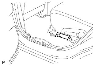 |
Remove the 2 clips and reclining hinge cover.
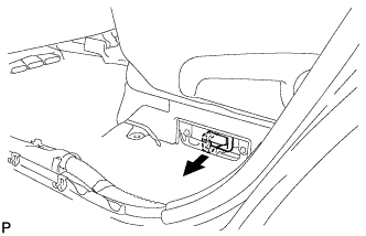 |
Wear insulated glove and remove the service plug grip, after sliding up the lever of the service plug grip.
| 4. REMOVE FRONT WIPER ARM AND BLADE ASSEMBLY LH |
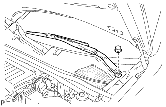 |
Remove the nut, and the front wiper arm and blade assembly LH.
| 5. REMOVE FRONT WIPER ARM AND BLADE ASSEMBLY RH |
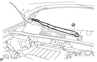 |
Remove the nut, and the front wiper arm and blade assembly RH.
| 6. REMOVE COWL TOP VENTILATOR LOUVER SUB-ASSEMBLY |
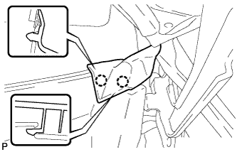 |
Disengage the 2 claws and disconnect the front fender to cowl side seal LH.
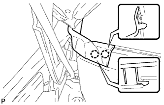 |
Disengage the 2 claws and disconnect the front fender to cowl side seal RH.
Remove the 2 clips.
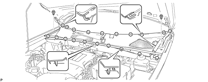
Disengage the 20 claws and remove the cowl top ventilator louver sub-assembly.
| 7. REMOVE WINDSHIELD WIPER MOTOR AND LINK ASSEMBLY |
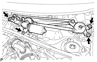 |
Disconnect the connector.
Remove the 4 bolts, and the windshield wiper motor and link assembly.
| 8. REMOVE OUTER COWL TOP PANEL SUB-ASSEMBLY |
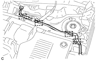 |
Disengage the 4 clamps and separate the wiper wire harness from the outer cowl top panel sub-assembly.
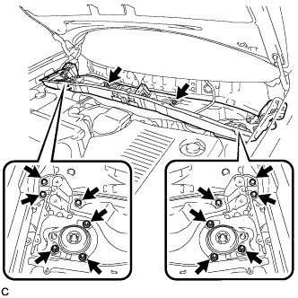 |
Remove the 8 bolts, 6 nuts, and the outer cowl top panel sub-assembly.
| 9. REMOVE NO. 2 ENGINE ROOM SIDE COVER LH |
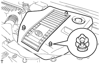 |
Remove the engine room side cover.
| 10. REMOVE COOL AIR INTAKE DUCT SEAL |
Remove the 11 clips and cool air intake duct seal.
| 11. REMOVE AIR CLEANER CAP SUB-ASSEMBLY |
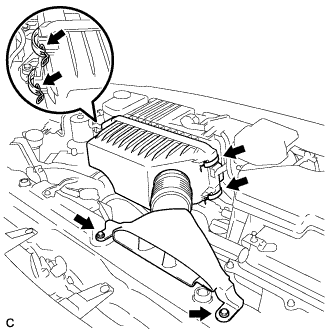 |
Remove the 2 bolts, 4 clamps and air cleaner cap sub-assembly.
Remove the air cleaner filter element from the air cleaner case.
| 12. REMOVE AIR CLEANER CASE SUB-ASSEMBLY |
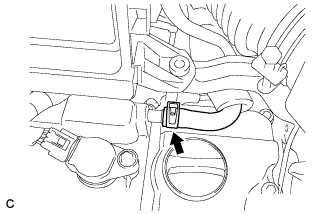 |
Separate the No. 1 ventilation hose.
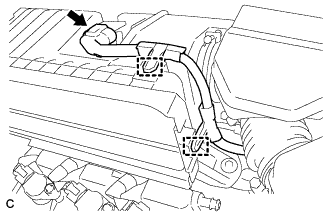 |
Disconnect the intake air flow meter connector.
Disconnect the 2 wire harness clamps from the air cleaner case sub-assembly.
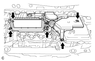 |
Remove the 5 bolts from the air cleaner case sub-assembly.
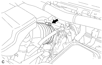 |
Loosen the hose clamp and separate the No. 1 air cleaner hose.
Remove the air cleaner case sub-assembly.
| 13. REMOVE INVERTER RESERVE TANK SUB-ASSEMBLY |
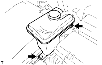 |
Remove the 2 bolts from the inverter reserve tank sub-assembly.
| 14. REMOVE INVERTER COVER |
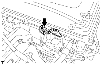 |
Remove the bolt and interlock bracket.
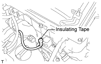 |
Insulate the removed terminal with insulating tape.
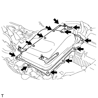 |
Remove the 12 bolts and inverter cover.
| 15. CHECK TERMINAL VOLTAGE |
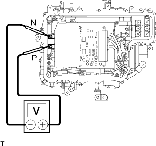 |
Using the voltmeter, measure the voltage between the terminals of the 2 phase connectors (N-P).
| 16. INSTALL INVERTER COVER |
|
Install the inverter cover with the 12 bolts to the inverter with converter assembly.
|
Install the interlock bracket with the bolt to the inverter with converter assembly.
| 17. INSTALL INVERTER RESERVE TANK SUB-ASSEMBLY |
|
Install the inverter reserve tank sub-assembly with the 2 bolts.
| 18. INSTALL AIR CLEANER CASE SUB-ASSEMBLY |
|
Align the tab on the throttle body with the groove on the air cleaner hose and tighten the hose clamp.
|
Install the air cleaner case sub-assembly with the 5 bolts.
|
Connect the intake air flow meter connector.
Connect the 2 wire harness clamps to the air cleaner case.
|
Connect the No. 1 ventilation hose.
| 19. INSTALL AIR CLEANER CAP SUB-ASSEMBLY |
Install the air cleaner filter element to the air cleaner case.
|
Install the 2 bolts, 4 clamps and air cleaner cap sub-assembly.
| 20. INSTALL OUTER COWL TOP PANEL SUB-ASSEMBLY |
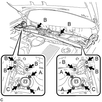 |
Install the outer cowl top panel sub-assembly with the 8 bolts and 6 nuts.
|
Engage the 4 clamps.
| 21. INSTALL WINDSHIELD WIPER MOTOR AND LINK ASSEMBLY |
|
Install the windshield wiper motor and link assembly with the 4 bolts.
Connect the connector.
| 22. INSTALL COWL TOP VENTILATOR LOUVER SUB-ASSEMBLY |
Engage the 20 claws.
Install the cowl top ventilator louver sub-assembly with the 2 clips.
|
Engage the 2 claws and connect the front fender to cowl side seal LH.
|
Engage the 2 claws and connect the front fender to cowl side seal RH.
| 23. INSTALL FRONT WIPER ARM AND BLADE ASSEMBLY RH |
Operate the wiper and stop the windshield wiper motor at the automatic stop position.
When reinstalling:
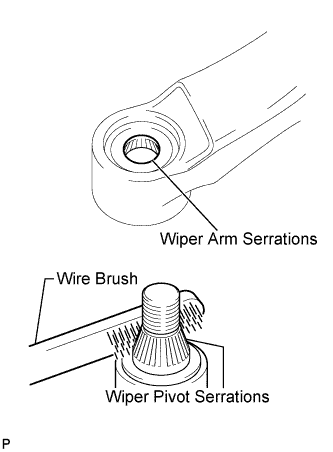 |
Clean the wiper arm serrations.
Clean the wiper pivot serrations with a wire brush.
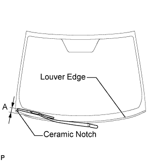 |
Install the front wiper arm and blade assembly RH with the nut to the position shown in the illustration.
| Area | Measurement |
| A | 25.6 mm (1.00 in.) |
| 24. INSTALL FRONT WIPER ARM AND BLADE ASSEMBLY LH |
Operate the wiper and stop the windshield wiper motor at the automatic stop position.
When reinstalling:
|
Clean the wiper arm serrations.
Clean the wiper pivot serrations with a wire brush.
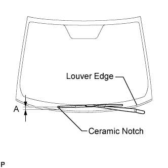 |
Install the front wiper arm and blade assembly LH with the nut to the position shown in the illustration.
| Area | Measurement |
| A | 31.9 mm (1.26 in.) |
Operate the front wipers while spraying washer fluid onto the windshield glass. Make sure that the front wipers function properly and the wipers do not come into contact with the vehicle body.
| 25. INSTALL COOL AIR INTAKE DUCT SEAL |
Install the cool air intake duct seal with the 11 clips.
| 26. INSTALL NO. 2 ENGINE ROOM SIDE COVER LH |
|
Fit the clips and install the No. 2 engine room side cover LH.
| 27. DRAIN HYBRID TRANSAXLE FLUID |
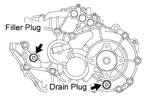 |
Using a socket hexagon wrench 10 mm, remove the filler plug and gasket.
Using a socket hexagon wrench 10 mm, remove the drain plug and gasket.
Using a socket hexagon wrench 10 mm, install the drain plug and a new gasket.
| 28. REMOVE REAR WHEELS |
| 29. REMOVE EXHAUST PIPE ASSEMBLY |
| 30. REMOVE REAR AXLE SHAFT LH NUT |
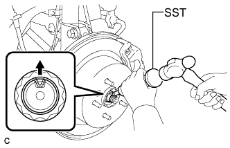 |
Using SST and a hammer, release the staked part of the rear axle shaft nut.
While applying the brakes, remove the rear axle shaft nut.
| 31. REMOVE REAR AXLE SHAFT RH NUT |
| 32. SEPARATE REAR STRUT ROD ASSEMBLY |
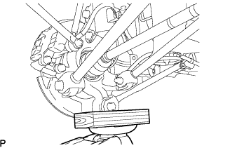 |
Support the rear axle carrier with a wooden block placed between the jack and axle carrier.
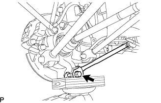 |
Remove the bolt, nut and rear strut rod assembly.
| 33. SEPARATE REAR NO. 1 SUSPENSION ARM ASSEMBLY LH |
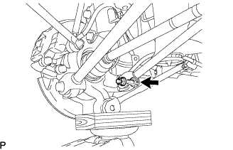 |
Remove the bolt and nut, and separate the rear No. 1 suspension arm assembly LH.
| 34. SEPARATE REAR NO. 1 SUSPENSION ARM ASSEMBLY RH |
| 35. SEPARATE REAR NO. 2 SUSPENSION ARM ASSEMBLY LH |
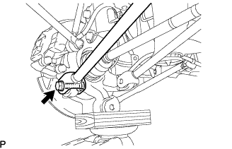 |
Remove the bolt and nut, and separate the rear No. 2 suspension arm assembly LH.
| 36. SEPARATE REAR NO. 2 SUSPENSION ARM ASSEMBLY RH |
| 37. REMOVE REAR DRIVE SHAFT ASSEMBLY LH |
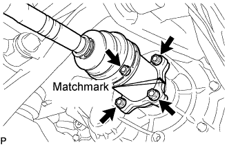 |
Put matchmarks on the rear drive shaft assembly and differential side gear shaft.
Remove the 4 nuts, washers and rear drive shaft assembly.
| 38. REMOVE REAR DRIVE SHAFT ASSEMBLY RH |
| 39. SEPARATE NO. 3 PARKING BRAKE CABLE ASSEMBLY |
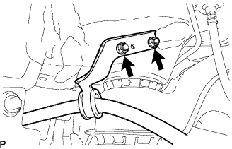 |
Remove the 2 nuts, and separate the No. 3 parking brake cable assembly.
| 40. SEPARATE NO. 2 PARKING BRAKE CABLE ASSEMBLY |
| 41. SEPARATE NO. 3 WIRE FRAME |
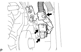 |
Disconnect the 2 connectors and clamp.
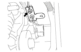 |
Remove the nut, and separate the ground cable.
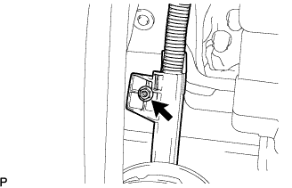 |
Remove the nut, and separate the wire harness clamp.
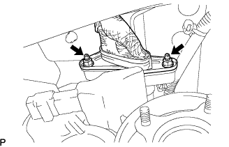 |
Wear insulated gloves. Remove the 2 nuts, and separate the No. 3 frame wire from the rear traction motor.
| 42. REMOVE REAR SUSPENSION MEMBER SUB-ASSEMBLY |
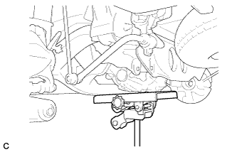 |
Support the rear suspension member with a jack.
Remove the 4 nuts, 2 bolts and 2 rear lower suspension member stopper retainers.
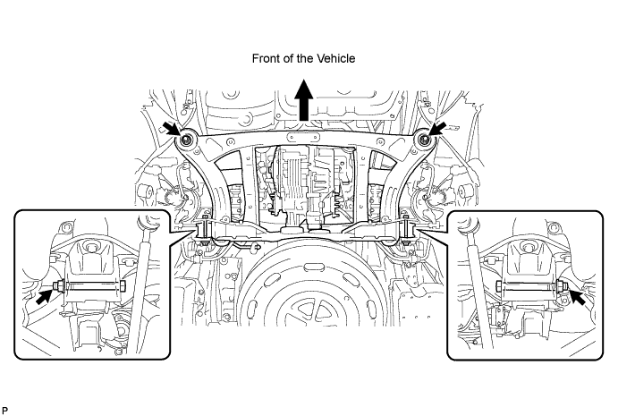
Lower the rear suspension member.
Remove the 2 rear upper suspension member stoppers.
| 43. REMOVE REAR TRACTION WITH TRANSAXLE MOTOR ASSEMBLY |
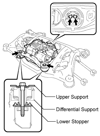 |
Remove the 4 bolts and rear traction with transaxle motor assembly.
| 44. REMOVE FRONT DIFFERENTIAL SUPPORT ASSEMBLY |
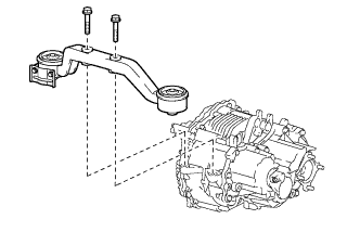 |
Remove the 2 bolts and front differential support assembly.
| 45. REMOVE EXTENSION WIRE ASSEMBLY |
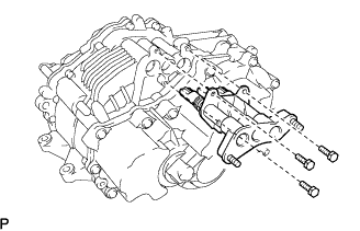 |
Remove the 3 bolts and extension wire assembly.
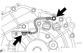 |
Remove the bolt, nut, ground cable and wire harness clamp bracket.
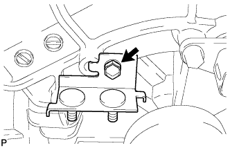 |
Remove the bolt and wire harness clamp bracket.
| 46. REMOVE BREATHER PLUG |
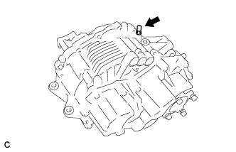 |
Remove the breather plug.