| B |  |
| GO TO DTC CHART (Click here) |
DTC P0A78-806 Drive Motor "A" Inverter Performance |
DTC P0A78-807 Drive Motor "A" Inverter Performance |
DTC P0A78-808 Drive Motor "A" Inverter Performance |
| DTC No. | INF Code | DTC Detection Condition | Trouble Area |
| P0A78 | 806 | Abnormal MG2 current value detection (MG ECU malfunction) |
|
| 807 | Abnormal MG2 current value detection (inverter malfunction) | ||
| 808 | Abnormal MG2 current value detection (hybrid vehicle transaxle malfunction) |
| Related DTCs | P0A78 (INF 806/807/808): Motor inverter / Motor inverter abnormal current |
| Required sensors / components | Motor inverter |
| Frequency of operation | Continuous |
| Duration | TMC's intellectual property |
| MIL operation | Immediately |
| Sequence of operation | None |
| The monitor will run whenever the DTCs listed are not present | TMC's intellectual property |
| Other conditions belong to TMC's intellectual property | - |
| Motor inverter | Abnormal current |
| Motor inverter | DTC P0A78 (INF 806/807/808) is not detected |
| 1.CHECK DTC OUTPUT (HV) |
Connect the Techstream to the DLC3.
Turn the power switch on (IG).
Select the following menu items: Powertrain / Hybrid Control / Trouble Codes.
Check if DTCs are output.
| Result | Proceed to |
| P0A78-806, 807 or 808 only is output. | A |
| Any of the following DTCs are also output. | B |
| DTC No. | Relevant Diagnosis |
| P0A1B (all INF codes) *1 | Drive Motor "A" Control Module |
| P0A1D (all INF codes) *1 | Hybrid Powertrain Control Module |
| P0A3F-243 | Drive Motor "A" Position Sensor Circuit |
| P0A40-500 | Drive Motor "A" Position Sensor Circuit Range / Performance |
| P0A41-245 | Drive Motor "A" Position Sensor Circuit Low |
| P0A60 (all INF codes) *1 | Drive Motor "A" Phase V Current |
| P0A63 (all INF codes) *1 | Drive Motor "A" Phase W Current |
| P0A78-266, 267, 272, 278, 279, 280, 282, 283, 284, 285, 286, 287, 304, 305, 306, 503, 504, 505, 506, 508, 510, 523, 586 | Drive Motor "A" Inverter Performance |
| P0A90-251, 509 | Drive Motor "A" Performance |
|
| ||||
| A | |
 |
| 2.CHECK CONNECTOR CONNECTION CONDITION (MG ECU CONNECTOR) |
Turn the power switch off.
Remove the service plug grip (Click here).
Remove the inverter cover (Click here).
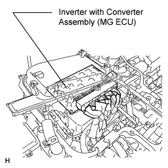 |
Check the connections of the MG ECU connectors.
|
| ||||
| OK | |
|
| 3.CHECK INVERTER WITH CONVERTER ASSEMBLY (MG2) |
Check that the service plug grip is not installed.
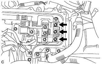 |
Check that the bolts for the three-phase AC cables are tightened to the specified torque, the three-phase AC cables are connected securely, and there are no contact problems.
Check for arc marks at the bolts for the motor cable.
| Result | Proceed to | |
| The terminals are connected securely and there are no contact problems. | There are no arc marks. | A |
| The terminals are not connected securely and there is a contact problem. | There are arc marks. | B |
| The terminals are not connected securely and there is a contact problem. | There are no arc marks. | C |
| The terminals are connected securely and there are no contact problems. | There are arc marks. | B |
|
| ||||
|
| ||||
| A | |
|
| 4.CHECK HYBRID VEHICLE TRANSAXLE ASSEMBLY (MG2) |
Check that the service plug grip is not installed.
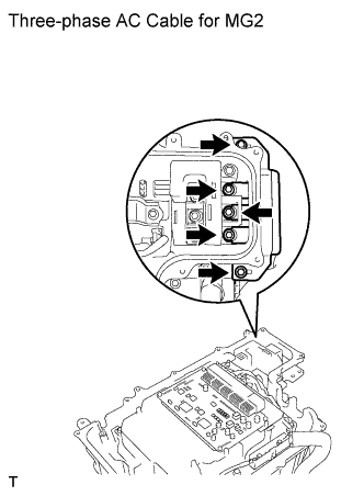 |
Disconnect the three-phase AC cable for MG2 from the inverter with converter assembly.
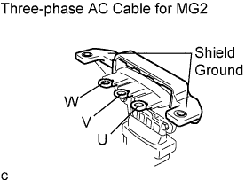 |
Using a milliohmmeter, measure the resistance according to the value(s) in the table below.
| Tester Connection | Condition | Specified Condition |
| U - V | Power switch off (68°F (20°C)) | 52.4 to 58.4 mΩ or less |
| V - W | Power switch off (68°F (20°C)) | 50.5 to 56.5 mΩ or less |
| W - U | Power switch off (68°F (20°C)) | 50.5 to 56.5 mΩ or less |
To correct the variation of the measured resistance due to temperature, use the following formula to calculate the resistance at 68°F (20°C).
Calculate the difference between the maximum and minimum resistance.
Using a megohmmeter set to 500 V, measure the insulation resistance according to the value(s) in the table below.
| Tester Connection | Switch Condition | Specified Condition |
| MG2 U terminal - Body ground and shield ground | Power switch off | 100 MΩ or higher |
| MG2 V terminal - Body ground and shield ground | Power switch off | 100 MΩ or higher |
| MG2 W terminal - Body ground and shield ground | Power switch off | 100 MΩ or higher |
|
| ||||
| OK | |
|
| 5.CHECK HARNESS AND CONNECTOR (MG ECU - MOTOR RESOLVER) |
Check that the service plug grip is not installed.
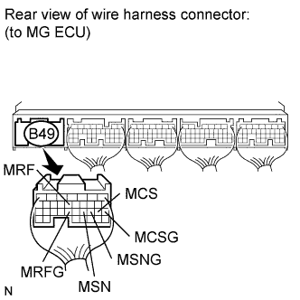 |
Disconnect the B49 connector from the MG ECU.
Turn the power switch on (IG).
Measure the voltage according to the value(s) in the table below.
| Tester Connection | Switch Condition | Specified Condition |
| B49-13 (MRF) - Body ground | Power switch on (IG) | Below 1 V |
| B49-23 (MRFG) - Body ground | Power switch on (IG) | Below 1 V |
| B49-21 (MSN) - Body ground | Power switch on (IG) | Below 1 V |
| B49-20 (MSNG) - Body ground | Power switch on (IG) | Below 1V |
| B49-19 (MCS) - Body ground | Power switch on (IG) | Below 1 V |
| B49-18 (MCSG) - Body ground | Power switch on (IG) | Below 1 V |
Turn the power switch off.
Measure the resistance according to the value(s) in the table below.
| Tester Connection | Switch Condition | Specified Condition |
| B49-13 (MRF) - B49-23 (MRFG) | Power switch off | 7.65 to 10.2 Ω |
| B49-21 (MSN) - B49-20 (MSNG) | Power switch off | 12.6 to 16.8 Ω |
| B49-19 (MCS) - B49-18 (MCSG) | Power switch off | 12.6 to 16.8 Ω |
Measure the resistance according to the value(s) in the table below.
| Tester Connection | Switch Condition | Specified Condition |
| B49-13 (MRF) or B49-23 (MRFG) - Body ground and other terminals | Power switch off | 10 kΩ or higher |
| B49-21 (MSN) or B49-20 (MSNG) - Body ground and other terminals | Power switch off | 10 kΩ or higher |
| B49-19 (MCS) or B49-18 (MCSG) - Body ground and other terminals | Power switch off | 10 kΩ or higher |
|
| ||||
| OK | |
|
| 6.CHECK CONNECTOR CONNECTION CONDITION (MOTOR RESOLVER CONNECTOR) |
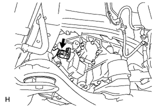 |
Check the connection of the motor resolver connector.
|
| ||||
| OK | ||
 | ||
| ||
| 7.CHECK CONNECTOR CONNECTION CONDITION (MOTOR RESOLVER CONNECTOR) |
|
Check the connection of the motor resolver connector.
|
| ||||
| OK | |
|
| 8.CHECK MOTOR RESOLVER |
Disconnect the B54 motor resolver connector.
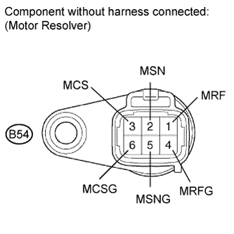 |
Measure the resistance according to the value(s) in the table below.
| Tester Connection | Switch Condition | Specified Condition |
| B54-1 (MRF) - B54-4 (MRFG) | Power switch off | 7.65 to 10.2 Ω |
| B54-2 (MSN) - B54-5 (MSNG) | Power switch off | 12.6 to 16.8 Ω |
| B54-3 (MCS) - B54-6 (MCSG) | Power switch off | 12.6 to 16.8 Ω |
Using a megohmmeter set to 500 V, measure the insulation resistance according to the value(s) in the table below.
| Tester Connection | Switch Condition | Specified Condition |
| B54-1 (MRF) - B54-2 (MSN) | Power switch off | 10 MΩ or higher |
| B54-1 (MRF) - B54-3 (MCS) | Power switch off | 10 MΩ or higher |
| B54-2 (MSN) - B54-3 (MCS) | Power switch off | 10 MΩ or higher |
| B54-4 (MRFG) - B54-5 (MSNG) | Power switch off | 10 MΩ or higher |
| B54-4 (MRFG) - B54-6 (MCSG) | Power switch off | 10 MΩ or higher |
| B54-5 (MSNG) - B54-6 (MCSG) | Power switch off | 10 MΩ or higher |
| Each terminal listed above - Transaxle housing | Power switch off | 10 MΩ or higher |
|
| ||||
| OK | ||
| ||
| ||
