| B |  |
| GO TO DTC CHART (Click here) |
DTC P0A92-261 Hybrid Generator Performance |
| DTC No. | INF Code | DTC Detection Condition | Trouble Area |
| P0A92 | 261 | Generator magnetic force deterioration or same phase short circuit |
|
| Related DTCs | P0A92 (INF 261): Magnetic force deterioration / Same phase short circuit |
| Required sensors / components | Hybrid vehicle generator, inverter, motor resolver |
| Frequency of operation | Continuous |
| Duration | TMC's intellectual property |
| MIL operation | Immediately |
| Sequence of operation | None |
| The monitor will run whenever the DTCs listed are not present | TMC's intellectual property |
| Other conditions belong to TMC's intellectual property | - |
| TMC's intellectual property | - |
| Hybrid vehicle generator | DTC P0A92 (INF 261) is not detected |
| 1.CHECK DTC OUTPUT (HV) |
Connect the Techstream to the DLC3.
Turn the power switch on (IG).
Select the following menu items: Powertrain / Hybrid Control / Trouble Codes.
Check if DTCs are output.
| Result | Proceed to |
| P0A92-261 only is output. | A |
| Any of the following DTCs are also output. | B |
| DTC No. | Relevant Diagnosis |
| P0A1A (all INF codes) *1 | Generator Control Module |
| P0A1B (all INF codes) *1 | Drive Motor "A" Control Module |
| P0A1C (all INF codes) *1 | Drive Motor "B" Control Module |
| P0A1D (all INF codes) *1 | Hybrid Powertrain Control Module |
| P0A3F-243 | Drive Motor "A" Position Sensor Circuit |
| P0A40-500 | Drive Motor "A" Position Sensor Circuit Range / Performance |
| P0A41-245 | Drive Motor "A" Position Sensor Circuit Low |
| P0A45-669 | Drive Motor "B" Position Sensor Circuit |
| P0A46-671 | Drive Motor "B" Position Sensor Circuit Range / Performance |
| P0A47-670 | Drive Motor "B" Position Sensor Circuit Low |
| P0A4B-253 | Generator Position Sensor Circuit |
| P0A4C-513 | Generator Position Sensor Circuit Range / Performance |
| P0A4D-255 | Generator Position Sensor Circuit Low |
| P0A51-174 | Drive Motor "A" Current Sensor Circuit |
| P0A55-687 | Drive Motor "B" Current Sensor Circuit |
| P0A60 (all INF codes) *1 | Drive Motor "A" Phase V Current |
| P0A63 (all INF codes) *1 | Drive Motor "A" Phase W Current |
| P0A69 (all INF codes) *1 | Drive Motor "B" Phase V Current |
| P0A6C (all INF codes) *1 | Drive Motor "B" Phase W Current |
| P0A72 (all INF codes) *1 | Generator Phase V Current |
| P0A75 (all INF codes) *1 | Generator Phase W Current |
| P0A78-266, 267, 272, 278, 280, 283, 285, 304, 305, 306, 508, 510, 523, 586 | Drive Motor "A" Inverter Performance |
| P0A79-672, 690, 691, 697, 698, 701, 703 | Drive Motor "B" Inverter Performance |
| P0A7A-309, 321, 323, 325, 342, 343, 517, 520, 522 | Generator Inverter Performance |
| P0A90-509 | Drive Motor "A" Performance |
| P0A91-702 | Drive Motor "B" Performance |
| P0A92-521 | Hybrid Generator Performance |
| P0A94-545, 546, 551, 552, 558, 559, 561, 585, 587, 588, 589, 590 | DC / DC Converter Performance |
| P0AA6 (all INF codes) *1 | Hybrid Battery Voltage System Isolation Fault |
| P3004-132 | Power Cable Malfunction |
| P3232-749 | Open or Short to B+ in Blocking of HV Gate Connection |
| P3233-750 | Short to B+ in Blocking of HV Gate Connection |
|
| ||||
| A | |
 |
| 2.REPRODUCTION TEST |
Connect the Techstream to the DLC3.
Leave the vehicle for 1 minute with the engine on (with MG1 rotating).
Check for HV system DTCs by following the prompts on Techstream screen.
| DTC output | Proceed to |
| P0A92-261 is output or no DTC is output | A |
| P0A7A-344 or P0A92-521 is output | B |
|
| ||||
| A | |
|
| 3.CHECK CONNECTOR CONNECTION CONDITION (MG ECU CONNECTOR) |
Turn the power switch off.
Remove the service plug grip (Click here).
Remove the inverter cover (Click here).
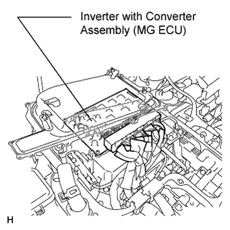 |
Check the connections of the MG ECU connectors.
|
| ||||
| OK | |
|
| 4.CHECK INVERTER WITH CONVERTER ASSEMBLY (MG1) |
Check that the service plug grip is not installed.
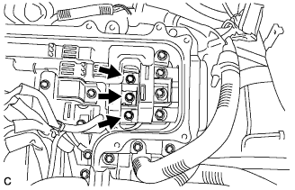 |
Check that the bolts for the three-phase AC cable for MG1 are tightened to the specified torque, the three-phase AC cable for MG1 is connected securely, and there are no contact problems.
Check for arc marks at the bolts for the generator cable.
| Result | Proceed to | |
| The terminals are connected securely and there are no contact problems. | There are no arc marks. | A |
| The terminals are not connected securely and there is a contact problem. | There are arc marks. | B |
| The terminals are not connected securely and there is a contact problem. | There are no arc marks. | C |
| The terminals are connected securely and there are no contact problems. | There are arc marks. | B |
|
| ||||
|
| ||||
| A | ||
 | ||
| ||