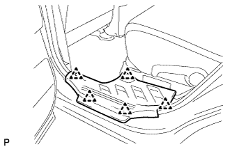
BRAKE PEDAL STROKE SENSOR > INSTALLATION |
| 1. INSTALL BRAKE PEDAL STROKE SENSOR |
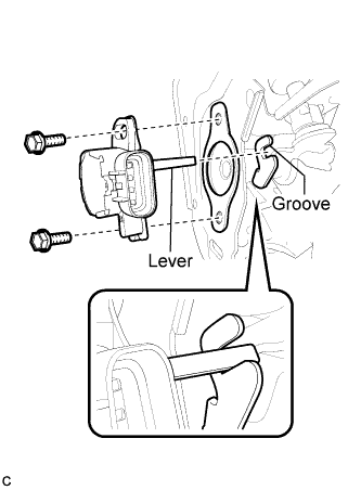
When installing a new brake pedal stroke sensor assembly:
![]() |
Connect the sensor connector.
Install a new sensor with the 2 bolts.
Firmly depress the brake pedal and break the sensor lever set pin.
Remove the broken lever set pin.
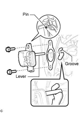
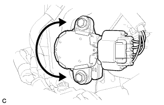
When reusing the brake pedal stroke sensor assembly:
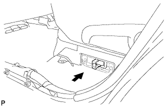
Connect the sensor connector.
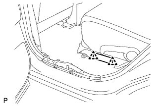
![]() |
Temporarily install the sensor with the 2 bolts.
Connect the cable to the negative battery terminal.
Connect the Techstream to the DLC3.
![]() |
Turn the power switch on (IG). Reading the value of the stroke sensor shown in Data List, turn the sensor slowly to the right and left to adjust the output voltage to the standard voltage.
| Tester Display | Measurement Item/Range | Normal Condition | Diagnostic Note |
| Stroke Sensor | Stroke sensor / min.: 0 V, max.: 5 V | When brake pedal is released: 0.7 to 1.3 V | - |
Tighten the 2 bolts.
Disconnect the cable from the negative battery terminal.
Disconnect the Techstream.
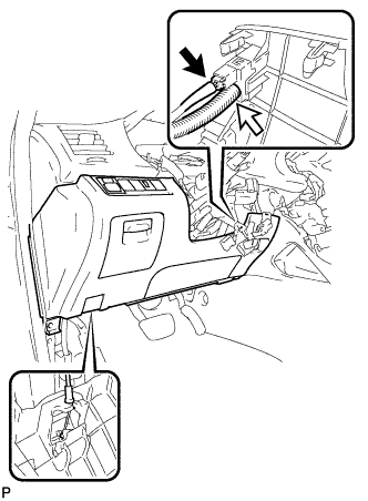
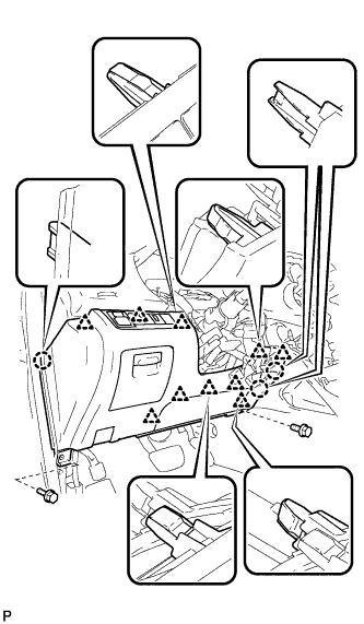
| 2. INSTALL LOWER INSTRUMENT PANEL FINISH PANEL SUB-ASSEMBLY |
![]() |
Connect the hood lock control cable assembly.
Connect each connector and the aspirator duct.
![]() |
Engage the 3 claws and 10 clips.
Install the lower instrument panel finish panel sub-assembly with the 2 bolts <B>.
| 3. INSTALL COWL SIDE TRIM SUB-ASSEMBLY |
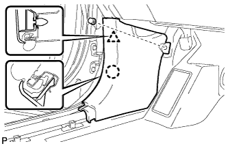
![]() |
Engage the claw and clip, install the cowl side trim sub-assembly LH.
Install the clip.
| 4. INSTALL FRONT DOOR SCUFF PLATE LH |
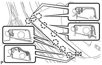
![]() |
Engage the guide and the 8 claws, and install the front door scuff plate LH.
| 5. INSTALL SERVICE PLUG GRIP |
![]() |
Wear insulated gloves, then insert the service plug.
Push down on the grip to lock.
![]() |
Close the reclining hinge cover.
![]() |
Close the rear door scuff plate LH.
| 6. CONNECT CABLE TO NEGATIVE BATTERY TERMINAL |
| 7. CHECK AND CLEAR DTC |
Check and clear the DTCs (Click here).
| 8. PERFORM LINEAR VALVE OFFSET LEARNING |
Perform linear valve offset learning (Click here).