 |
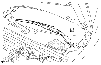
Remove the nut, and the front wiper arm and blade assembly LH.
CYLINDER HEAD GASKET (for Bank 1) > REMOVAL |
| 1. PRECAUTION |
Check for DTCs (Click here).
| 2. REMOVE FRONT WIPER ARM AND BLADE ASSEMBLY LH |
|
Remove the nut, and the front wiper arm and blade assembly LH.
| 3. REMOVE FRONT WIPER ARM AND BLADE ASSEMBLY RH |
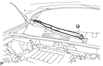 |
Remove the nut, and the front wiper arm and blade assembly RH.
| 4. REMOVE HOOD TO COWL TOP SEAL |
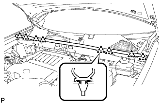 |
Disengage the 8 clips and remove the hood to cowl top seal.
| 5. REMOVE COWL TOP VENTILATOR LOUVER SUB-ASSEMBLY |
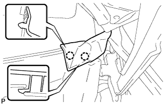 |
Disengage the 2 claws and disconnect the front fender to cowl side seal LH.
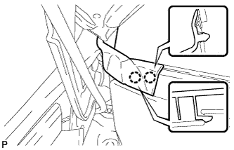 |
Disengage the 2 claws and disconnect the front fender to cowl side seal RH.
Remove the 2 clips.
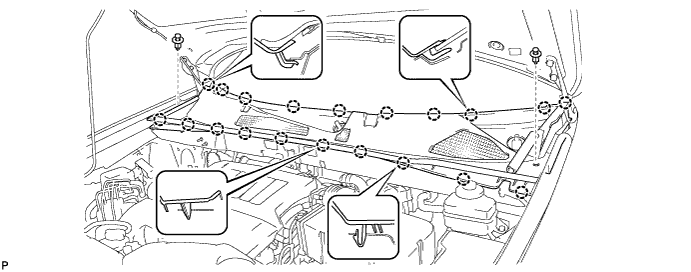
Disengage the 20 claws and remove the cowl top ventilator louver sub-assembly.
| 6. REMOVE WINDSHIELD WIPER MOTOR AND LINK ASSEMBLY |
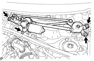 |
Disconnect the connector.
Remove the 4 bolts, and the windshield wiper motor and link assembly.
| 7. REMOVE OUTER COWL TOP PANEL SUB-ASSEMBLY |
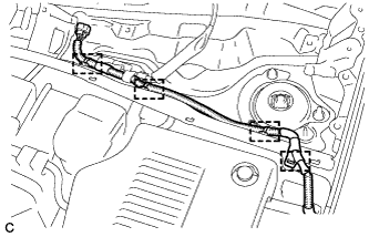 |
Disengage the 4 clamps and separate the wiper wire harness from the outer cowl top panel sub-assembly.
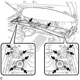 |
Remove the 8 bolts, 6 nuts, and the outer cowl top panel sub-assembly.
| 8. REMOVE NO. 2 ENGINE ROOM SIDE COVER LH |
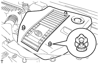 |
Remove the engine room side cover.
| 9. REMOVE DISCHARGE FUEL SYSTEM PRESSURE |
| 10. DRAIN COOLANT (for Engine) |
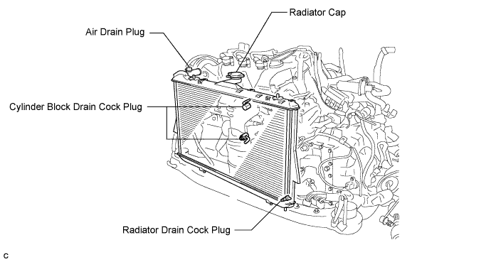
Loosen the radiator drain cock plug.
Loosen the cylinder block drain cock plugs.
Remove the radiator cap.
| 11. DRAIN ENGINE OIL |
Remove the oil filler cap.
Remove the oil drain plug and drain the oil into a container.
Clean and install the oil pan drain plug with a new gasket.
| 12. REMOVE FRONT WHEEL RH |
| 13. REMOVE NO. 1 ENGINE UNDER COVER |
Remove the 6 bolts, 2 screws, 2 clips and No. 1 engine under cover.
| 14. REMOVE FRONT FENDER LINER RH |
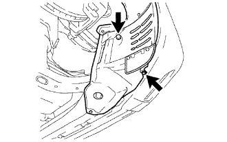 |
Remove the screw and clip, and separate the front fender liner.
| 15. REMOVE FRONT FENDER APRON SEAL RH |
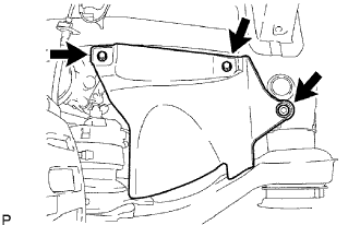 |
Remove the 2 bolts, clip and fender apron seal RH.
| 16. REMOVE NO. 2 ENGINE UNDER COVER |
Remove the 4 bolts and No. 2 engine under cover.
| 17. REMOVE BATTERY |
Disconnect the battery terminal.
Remove the bolt and battery clamp.
Remove the battery and battery tray.
| 18. REMOVE BATTERY CARRIER SUB-ASSEMBLY |
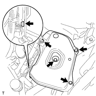 |
Remove the 5 bolts and battery carrier.
| 19. REMOVE AIR CLEANER CAP SUB-ASSEMBLY |
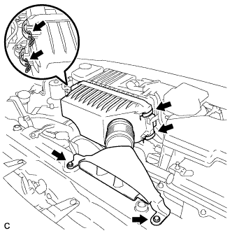 |
Remove the 2 bolts, 4 clamps and air cleaner cap sub-assembly.
Remove the air cleaner filter element from the air cleaner case.
| 20. REMOVE AIR CLEANER CASE SUB-ASSEMBLY |
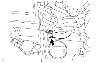 |
Separate the No. 1 ventilation hose.
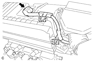 |
Disconnect the intake air flow meter connector.
Disconnect the 2 wire harness clamps from the air cleaner case sub-assembly.
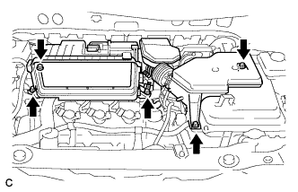 |
Remove the 5 bolts from the air cleaner case sub-assembly.
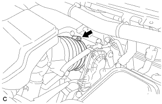 |
Loosen the hose clamp and separate the No. 1 air cleaner hose.
Remove the air cleaner case sub-assembly.
| 21. REMOVE SERVICE PLUG GRIP |
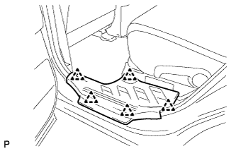 |
Remove the 5 clips and door scuff plate LH.
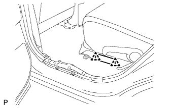 |
Remove the 2 clips and reclining hinge cover.
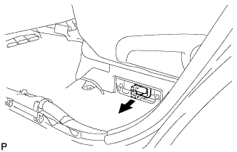 |
Wear insulated glove and remove the service plug grip, after sliding up the lever of the service plug grip.
| 22. REMOVE INVERTER WITH CONVERTER ASSEMBLY |
| 23. REMOVE EMISSION CONTROL VALVE SET |
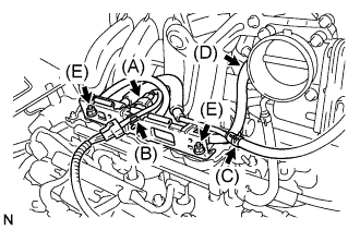 |
Disconnect the VSV connector (A).
Remove the wire harness clamp (B).
Disconnect the No. 1 fuel vapor feed hose (C).
Disconnect the No. 2 fuel vapor feed hose (D).
Remove the 2 nuts (E), then remove the emission control valve set.
| 24. REMOVE INTAKE AIR SURGE TANK |
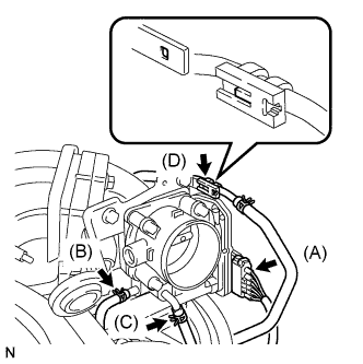 |
Disconnect the throttle motor connector (A).
Separate the No. 2 water by-pass hose (B).
Separate the No. 3 water by-pass hose (C).
Separate the fuel vapor feed hose (D).
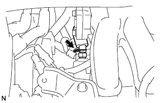 |
Disconnect the ventilation hose.
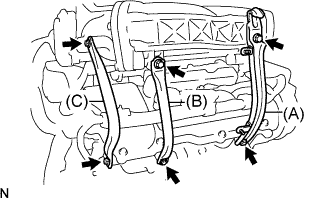 |
Remove the 2 bolts and No. 1 engine hanger (A).
Remove the 2 bolts and No. 1 surge tank stay (B).
Remove the 2 bolts and No. 2 surge tank stay (C).
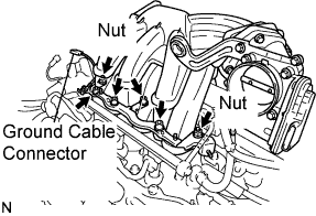 |
Disconnect the ground cable connector.
Using a socket hexagon wrench 8 mm, remove the 4 bolts.
Remove the 2 nuts, then remove the emission control valve bracket and the intake air surge tank.
Remove the gasket from the intake air surge tank.
| 25. DISCONNECT NO. 1 FUEL PIPE SUB-ASSEMBLY |
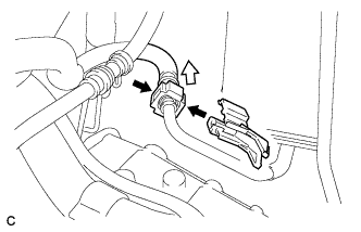 |
Remove the EFI fuel pipe clamp.
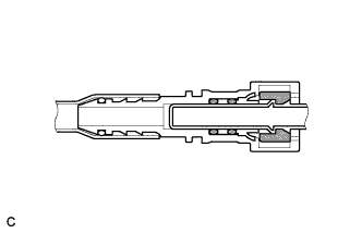 |
Pinch the retainer as illustrated, then pull out the fuel tube connector from the pipe.
| 26. DISCONNECT INLET HEATER WATER HOSE |
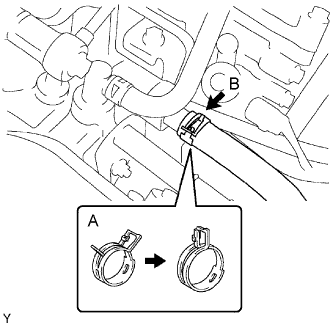 |
Lock the hose clamp as shown in the illustration (A).
Disconnect the inlet heater water hose (B).
| 27. REMOVE INTAKE MANIFOLD |
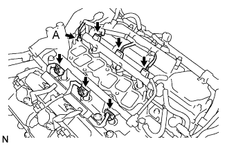 |
Remove the nut and disconnect the ground cable (A).
Disconnect the 6 fuel injector connectors.
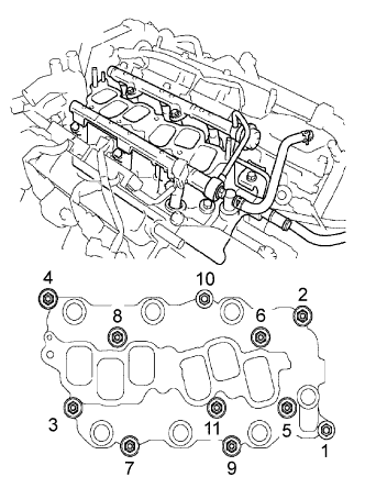 |
In order to remove the intake manifold, using several steps, remove the 9 bolts and 2 nuts in the sequence shown in the illustration.
| 28. DISCONNECT INLET RADIATOR HOSE |
| 29. REMOVE OUTLET WATER |
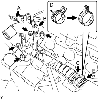 |
Disconnect the ground cable connector (A).
Disconnect the engine coolant temperature sensor connector (B).
Remove the clamp (C).
Remove the 2 bolts, 2 nuts and 2 washers.
Lock the hose clamp as shown in the illustration (D) and remove the water outlet together with No. 1 water by-pass hose (E).
Remove the 2 gaskets from the 2 cylinder heads.
| 30. SEPARATE BRAKE MASTER CYLINDER RESERVOIR SUB-ASSEMBLY |
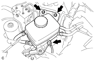 |
Disconnect the connector.
Remove the 2 nuts and separate the brake master cylinder reservoir.
| 31. REMOVE AIR CLEANER BRACKET |
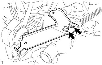 |
Remove the 2 bolts and air cleaner bracket.
| 32. REMOVE ENGINE MOVING CONTROL ROD |
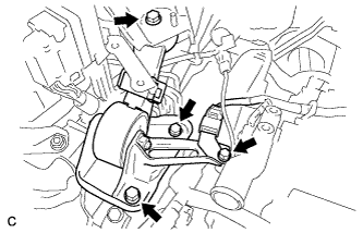 |
Remove the 4 bolts, the engine moving control rod and the bracket.
| 33. REMOVE NO. 2 ENGINE MOUNTING STAY |
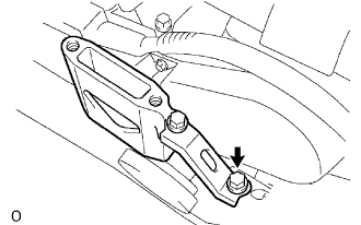 |
Remove the bolt, the No. 2 engine mounting stay and the No. 2 engine mounting bracket.
| 34. REMOVE CRANKSHAFT PULLEY |
Remove the bolt and the timing belt plate.
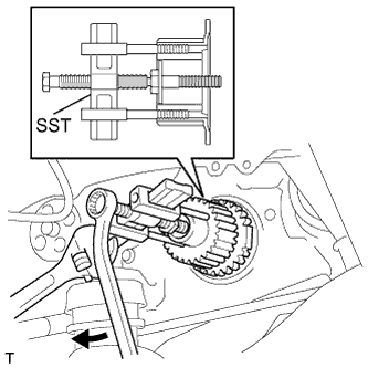 |
Install the pulley bolt to the crankshaft.
Using SST, remove the crankshaft timing pulley.
| 35. REMOVE NO. 1 TIMING BELT COVER |
Remove the 4 bolts and the No. 1 timing belt cover.
| 36. REMOVE NO. 2 TIMING BELT COVER |
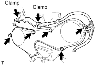 |
Disconnect the engine wire protector clamps from the No. 2 timing belt cover.
Remove the 5 bolts and the timing belt cover.
| 37. REMOVE ENGINE MOUNTING BRACKET RH |
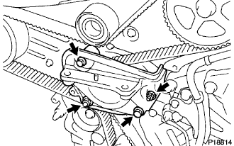 |
Remove the 2 bolts, 2 nuts and engine mounting bracket RH.
| 38. REMOVE NO. 2 TIMING BELT GUIDE |
| 39. REMOVE TIMING BELT |
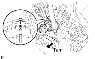 |
Set No. 1 cylinder to TDC/compression.
Temporarily install the crankshaft pulley bolt and washer to the crankshaft.
Turn the crankshaft clockwise, and align the timing mark of the crankshaft timing pulley with the oil pump body.
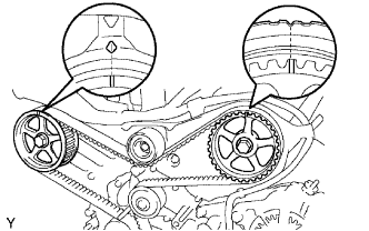 |
Check that the timing marks of the camshaft timing pulleys and No. 3 timing belt cover are aligned.
If not, turn the crankshaft 1 revolution (360°).
Remove the crankshaft pulley bolt.
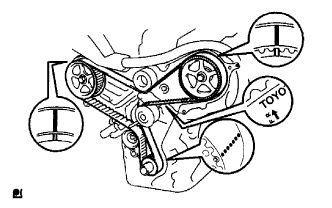 |
If reusing the timing belt, check that there are 4 installation marks on the timing belt as shown in the illustration.
If the installation marks have disappeared, put new installation marks on the timing belt before removing.
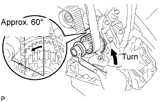 |
Set No. 1 cylinder to approximately 60° BTDC/compression.
Turn the crankshaft counterclockwise by approximately 60°.
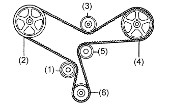 |
Remove the 2 bolts and No. 1 chain tensioner.
Remove the timing belt in the following order.
| 1st | No. 1 idler pulley |
| 2nd | RH camshaft timing pulley |
| 3rd | No. 2 idler pulley |
| 4th | LH camshaft timing pulley |
| 5th | Water pump pulley |
| 6th | Crankshaft timing pulley |
| 40. REMOVE NO. 2 TIMING BELT IDLER SUB-ASSEMBLY |
Remove the bolt and No. 2 timing belt idler sub-assembly.
| 41. REMOVE CAMSHAFT TIMING PULLEY |
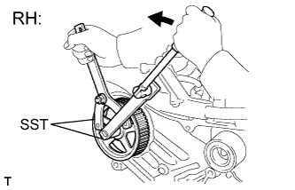 |
Using SST, remove the bolt and the RH timing pulley.
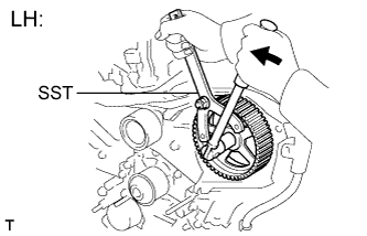 |
Using SST, remove the bolt and the LH timing pulley.
| 42. REMOVE NO. 3 TIMING BELT COVER |
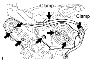 |
Disconnect the 2 engine wire harness clamps from the No. 3 timing belt cover.
Remove the 6 bolts and the timing belt cover.
| 43. REMOVE FRONT EXHAUST PIPE ASSEMBLY |
Disconnect the heated oxygen sensor connector.
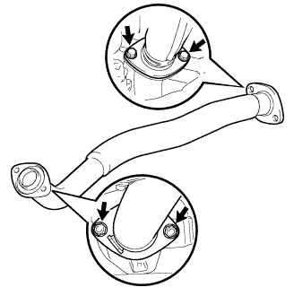 |
Remove the 2 bolts, 2 nuts and front exhaust pipe assembly.
Remove the 2 gaskets.
| 44. REMOVE FRONT NO. 3 EXHAUST PIPE SUB-ASSEMBLY |
Disconnect the heated oxygen sensor connector.
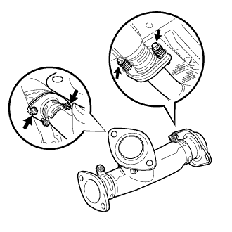 |
Remove the 2 bolts, 2 nuts and front No. 3 exhaust pipe sub-assembly.
Remove the 2 gaskets.
| 45. REMOVE NO. 1 EXHAUST MANIFOLD HEAT INSULATOR |
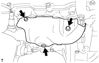 |
Remove the 3 bolts and No. 1 exhaust manifold heat insulator.
| 46. REMOVE MANIFOLD STAY |
Remove the 2 bolts and manifold stay.
| 47. REMOVE EXHAUST MANIFOLD SUB-ASSEMBLY RH |
Disconnect the heated oxygen sensor connector.
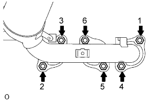 |
Using several steps, loosen and remove the 6 nuts in the sequence shown in the illustration.
Remove the exhaust manifold RH and the gasket from the cylinder head RH.
| 48. REMOVE IGNITION COIL ASSEMBLY |
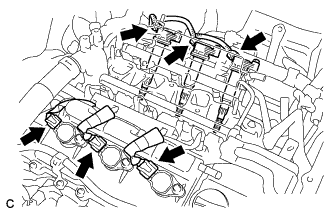 |
Disconnect the 6 ignition coil connectors.
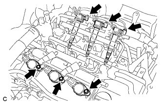 |
Remove the 6 bolts and 6 ignition coils.
| 49. REMOVE CYLINDER HEAD COVER SUB-ASSEMBLY |
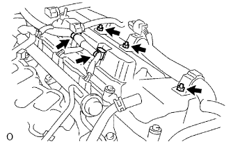 |
Remove the 2 engine wire harness clamps.
Remove the 3 nuts and disconnect the engine wire harness.
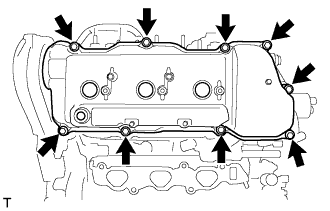 |
Remove the 9 bolts and the cylinder head cover.
| 50. REMOVE CAMSHAFT |
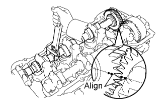 |
Align the timing marks (2-dot mark) of the camshaft drive and the driven gears by turning the camshaft with a wrench.
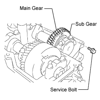 |
Secure the exhaust camshaft sub-gear to the main gear with a service bolt.
| Thread diameter | 6.0 mm (0.24 in.) |
| Thread pitch | 1.0 mm (0.04 in.) |
| Bolt length | 16 to 20 mm (0.63 to 0.79 in.) |
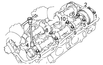 |
Using several steps, loosen and remove the 10 bearing cap bolts uniformly in the sequence shown in the illustration. Remove the 5 bearing caps and the camshaft.
| 51. REMOVE NO. 2 CAMSHAFT |
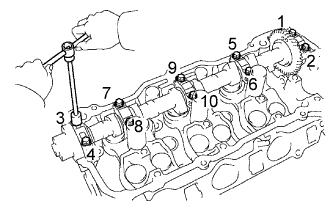 |
Using several steps, loosen and remove the 10 bearing cap bolts uniformly in the sequence shown in the illustration. Remove the 5 bearing caps and the No. 2 camshaft.
Remove the oil seal from the No. 2 camshaft.
| 52. REMOVE CYLINDER HEAD SUB-ASSEMBLY |
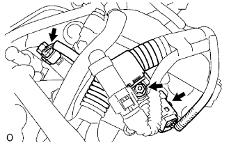 |
Disconnect the VVT sensor connector.
Disconnect the camshaft timing oil control valve connector.
Remove the nut and disconnect the engine wire harness clamp.
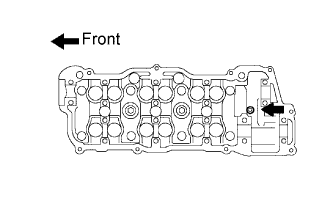 |
Using an 8 mm socket hexagon wrench, remove the hexagon bolt.
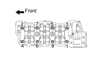 |
Using several steps, loosen the 8 cylinder head bolts uniformly in the sequence shown in the illustration. Remove the 8 cylinder head bolts and plate washers.
Remove the cylinder head.
| 53. REMOVE CYLINDER HEAD GASKET |