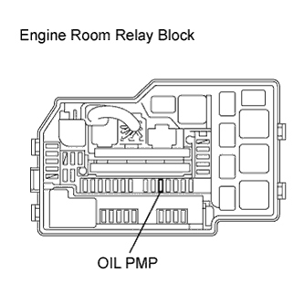
 |
Remove the OIL PMP fuse from the engine room relay block.
DTC P2603-768 Coolant Pump Control Circuit High |
| DTC No. | INF No. | DTC Detection Condition | Trouble Area |
| P2603 | 768 |
|
|
| 1.CHECK FUSE (OIL PMP) |
|
Remove the OIL PMP fuse from the engine room relay block.
Check for continuity of the OIL PMP fuse.
|
| ||||
| OK | |
 |
| 2.CHECK OIL PMP RELAY |
Remove the OIL PMP relay from the No. 3 engine room relay block.
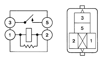 |
Measure the resistance according to the value(s) in the table below.
| Tester Connection | Condition | Specified Condition |
| 1 - 2 | Always | 130 to 235 Ω |
| 3 - 5 | Auxiliary battery voltage is not applied between terminals 1 and 2 | 10 kΩ or higher |
| Auxiliary battery voltage is applied between terminals 1 and 2 | Below 1 Ω |
|
| ||||
| OK | |
|
| 3.CHECK HARNESS AND CONNECTOR (HV CONTROL ECU - OIL PMP RELAY, OIL PMP RELAY - OIL PUMP) |
Disconnect the oil pump with motor assembly connector.
Disconnect connector A43 from the hybrid vehicle control ECU.
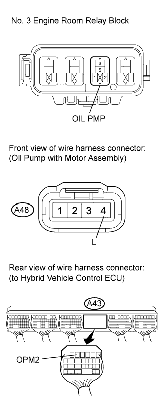 |
Measure the resistance according to the value(s) in the table below.
| Tester Connection | Switch Condition | Specified Condition |
| A43-5 (OPM2) - OIL PMP relay terminal 1 | Power switch off | Below 1 Ω |
| Tester Connection | Switch Condition | Specified Condition |
| A43-5 (OPM2) or OIL PMP relay terminal 1 - Body ground and other terminals | Power switch off | 10 kΩ or higher |
Measure the resistance according to the value(s) in the table below.
| Tester Connection | Switch Condition | Specified Condition |
| OIL PMP relay terminal 3 - A48-4 (L) | Power switch off | Below 1 Ω |
| Tester Connection | Switch Condition | Specified Condition |
| OIL PMP relay terminal 3 or A48-4 (L) - Body ground and other terminals | Power switch off | 10 kΩ or higher |
|
| ||||
| OK | |
|
| 4.CHECK HARNESS AND CONNECTOR (HYBRID VEHICLE CONTROL ECU - OIL PUMP) |
Turn the power switch on (IG).
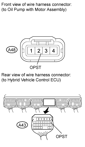 |
Measure the voltage according to the value(s) in the table below.
| Tester Connection | Switch Condition | Specified Condition |
| A43-7 (OPST) or A48-2 (OPST) - Body ground | Power switch on (IG) | Below 1 V |
Turn the power switch off.
Measure the resistance according to the value(s) in the table below.
| Tester Connection | Switch Condition | Specified Condition |
| A43-7 (OPST) - A48-2 (OPST) | Power switch off | Below 1 Ω |
|
| ||||
| OK | |
|
| 5.CHECK HYBRID VEHICLE CONTROL ECU |
Connect connector A43 to the hybrid vehicle control ECU.
Connect the Techstream to the DLC3.
Turn the power switch on (IG).
Select the following menu items: Powertrain / Hybrid Control / Active Test / Inspection Mode -2WD Inspection.
Turn the power switch on (READY).
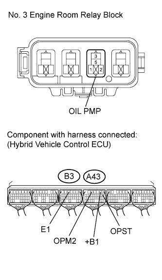 |
Measure the voltage according to the value(s) in the table below.
| Tester Connection | Switch Condition | Specified Condition |
| A43-5 (OPM2) - B3-5 (E1) | Power switch on (READY) | 11 to 14 V |
Turn the power switch off.
Measure the resistance according to the value(s) in the table below.
| Tester Connection | Switch Condition | Specified Condition |
| A43-7 (OPST) - A43-2 (+B1) | Power switch off | 10 kΩ or higher |
|
| ||||
| OK | ||
 | ||
| ||
