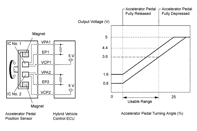
DTC P2120-111 Throttle / Pedal Position Sensor / Switch "D" Circuit |
DTC P2121-106 Throttle / Pedal Position Sensor / Switch "D" Circuit Range / Performance |
DTC P2121-114 Throttle / Pedal Position Sensor / Switch "D" Circuit Range / Performance |
DTC P2125-112 Throttle / Pedal Position Sensor / Switch "E" Circuit |
DTC P2126-109 Throttle / Pedal Position Sensor / Switch "E" Circuit Range / Performance |
DTC P2138-110 Throttle / Pedal Position Sensor / Switch "D" / "E" Voltage Correlation |
| DTC No. | INF Code | DTC Detection Condition | Trouble Area |
| P2120 | 111 | Main sensor value does not change while sub sensor value changes |
|
| P2121 | 106 | Internal error of main sensor | |
| 114 | Accelerator pedal does not smoothly return to its original position | ||
| P2125 | 112 | Sub sensor value does not change while main sensor value changes | |
| P2126 | 109 | Internal error of sub sensor | |
| P2138 | 110 | Difference between main sensor value and sub sensor value is large |
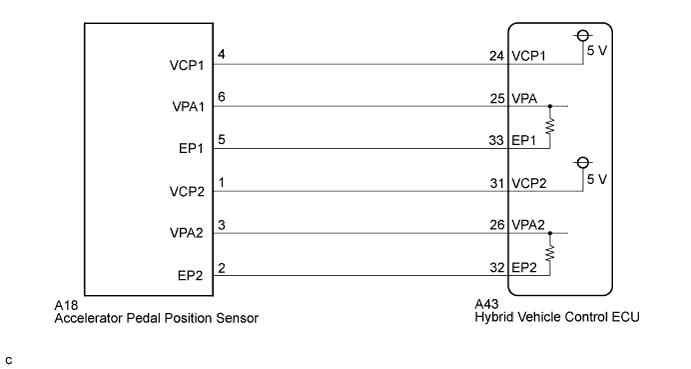
| 1.READ VALUE USING TECHSTREAM (ACCEL PEDAL POS #1, #2) |
 |
Connect the Techstream to the DLC3.
Turn the power switch on (IG).
Select the following menu items: Powertrain / Hybrid Control / Data List / Accel Pedal Pos #1 and Accel Pedal Pos #2.
Read the data list.
| Pedal Condition | Accel Pedal Pos #1 | Accel Pedal Pos #2 |
| Not depressed | (8 to 28%) 0.4 to 1.4 V | (20 to 44%) 1.0 to 2.2 V |
| Fully depressed | (62 to 92%) 3.1 to 4.6 V | (78 to 100%) 3.9 to 5.0 V |
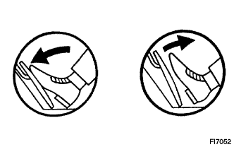
| Not depressed → Fully depressed → Not depressed (Accelerator pedal should be operated slowly) | Value changes progressively | Value changes progressively |
|
| ||||
| OK | ||
 | ||
| ||
| 2.CHECK HYBRID VEHICLE CONTROL ECU |
Disconnect the accelerator pedal position sensor connector.
Turn the power switch on (IG).
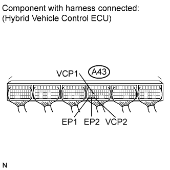 |
Measure the voltage according to the value(s) in the table below.
| Tester Connection | Switch Condition | Specified Condition |
| A43-24 (VCP1) - A43-33 (EP1) | Power switch on (IG) | 4.5 to 5.5 V |
| A43-31 (VCP2) - A43-32 (EP2) | Power switch on (IG) | 4.5 to 5.5 V |
|
| ||||
| OK | |
 |
| 3.CHECK HYBRID VEHICLE CONTROL ECU |
Connect the accelerator pedal position sensor connector.
Turn the power switch on (IG).
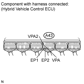 |
Measure the voltage according to the value(s) in the table below.
| Tester Connection | Condition | Specified Condition |
| A43-25 (VPA) - A43-33 (EP1) | Power switch on (IG) Accelerator pedal released | 0.4 to 1.4 V |
| Power switch on (IG) Accelerator pedal depressed | 3.1 to 4.6 V | |
| A43-26 (VPA2) - A43-32 (EP2) | Power switch on (IG) Accelerator pedal released | 1.0 to 2.2 V |
| Power switch on (IG) Accelerator pedal depressed | 3.9 to 5.5 V |
|
| ||||
| OK | ||
| ||
| ||
| 4.CHECK HARNESS AND CONNECTOR (HV CONTROL ECU - ACCELERATOR PEDAL POSITION SENSOR) |
Turn the power switch off.
Disconnect connector A43 from the hybrid vehicle control ECU.
Disconnect the accelerator pedal position sensor connector.
Turn the power switch on (IG).
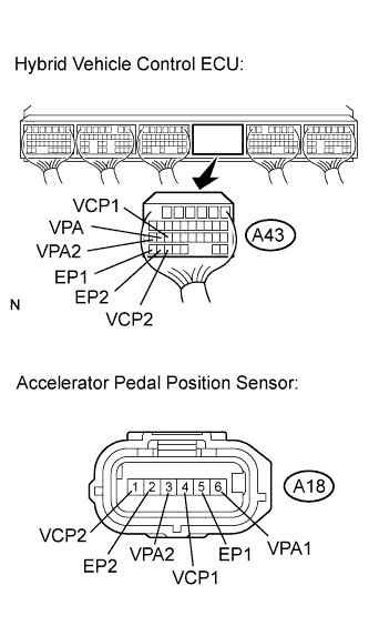 |
Measure the voltage according to the value(s) in the table below.
| Tester Connection | Switch Condition | Specified Condition |
| A43-25 (VPA) - Body ground | Power switch on (IG) | Below 1 V |
| A43-24 (VCP1) - Body ground | Power switch on (IG) | Below 1 V |
| A43-33 (EP1) - Body ground | Power switch on (IG) | Below 1 V |
| A43-26 (VPA2) - Body ground | Power switch on (IG) | Below 1 V |
| A43-31 (VCP2) - Body ground | Power switch on (IG) | Below 1 V |
| A43-32 (EP2) - Body ground | Power switch on (IG) | Below 1 V |
Turn the power switch off.
Measure the resistance according to the value(s) in the table.
| Tester Connection | Switch Condition | Specified Condition |
| A43-25 (VPA) - A18-6 (VPA1) | Power switch off | Below 1 Ω |
| A43-24 (VCP1) - A18-4 (VCP1) | Power switch off | Below 1 Ω |
| A43-33 (EP1) - A18-5 (EP1) | Power switch off | Below 1 Ω |
| A43-26 (VPA2) - A18-3 (VPA2) | Power switch off | Below 1 Ω |
| A43-31 (VCP2) - A18-1 (VCP2) | Power switch off | Below 1 Ω |
| A43-32 (EP2) - A18-2 (EP2) | Power switch off | Below 1 Ω |
| Tester Connection | Switch Condition | Specified Condition |
| A43-25 (VPA) or A18-6 (VPA1) - Body ground and other terminals | Power switch off | 10 kΩ or higher |
| A43-24 (VCP1) or A18-4 (VCP1) - Body ground and other terminals | Power switch off | 10 kΩ or higher |
| A43-33 (EP1) or A18-5 (EP1) - Body ground and other terminals | Power switch off | 10 kΩ or higher |
| A43-26 (VPA2) or A18-3 (VPA2) - Body ground and other terminals | Power switch off | 10 kΩ or higher |
| A43-31 (VCP2) or A18-1 (VCP2) - Body ground and other terminals | Power switch off | 10 kΩ or higher |
| A43-32 (EP2) or A18-2 (EP2) - Body ground and other terminals | Power switch off | 10 kΩ or higher |
|
| ||||
| OK | ||
| ||
| ||

