| B |  |
| GO TO DTC CHART (P0A1F-123) (Click here) |
DTC P0AD2-123 Hybrid Battery Pack Cooling Fan 3 Control Circuit Low |
| DTC No. | DTC Detection Condition | Trouble Area |
| P0AD2-123 | Voltage at each battery assembly (V0, V1 and V2) is out of the predetermined range in proportion to the target control voltage (1 trip detection). |
|
| 1.CHECK DTC OUTPUT (DTC P0A1F-123 IS OUTPUT) |
Connect the Techstream to the DLC3.
Turn the power switch on (IG).
Select the following menu items: Powertrain / Hybrid Control / Trouble Codes.
Read output DTCs (Click here).
| Result | Proceed to |
| P0A1F-123 is not output. | A |
| P0A1F-123 is also output. | B |
|
| ||||
| A | |
 |
| 2.CHECK DTC OUTPUT (HV) |
Connect the Techstream to the DLC3.
Turn the power switch on (IG).
Select the following menu items: Powertrain / Hybrid Control / Trouble Codes.
Read output DTCs.
| Result | Proceed to |
| P0AD2-123 is output | A |
| P0A84-123, P0A99-123, and P0AD2-123 are output | B |
|
| ||||
| A | |
|
| 3.CHECK BATTERY COOLING BLOWER ASSEMBLY |
Connect the Techstream to the DLC3.
Select the following menu items: Powertrain / Hybrid Control / Data List / VMF Fan Motor Voltage 1 to 3 and Temp of BATT TB 1 to 8.
Perform a road test and check that there is a malfunction in the VMF Fan motor Voltage 3 while the battery cooling blower assembly is operating. (*1)
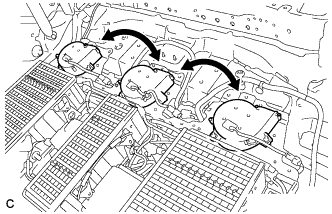 |
Remove the battery cover and replace the battery cooling blower assembly with another battery cooling blower assembly (Click here).
Install the battery cover.
Select the following menu items: Powertrain / Hybrid Control / Data List / VMF Fan Motor Voltage 1 to 3 and Temp of BATT TB 1 to 8.
Perform a road test and check that a malfunction in (*1) is reproduced in another battery cooling blower assembly.
| Result | Proceed to |
| The malfunction is reproduced in the same battery cooling blower. | A |
| The malfunction is reproduced in another battery cooling blower. | B |
|
| ||||
| A | |
|
| 4.CHECK HARNESS AND CONNECTOR (BATT FAN RELAY - BATTERY COOLING BLOWER ASSEMBLY) |
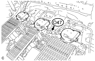 |
Disconnect the O47 battery cooling blower assembly connector.
Remove the BATT FAN relay.
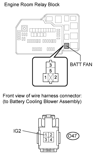 |
Measure the resistance according to the value(s) in the table below.
| Tester Connection | Switch Condition | Specified Condition |
| BATT FAN relay terminal 5 - O47-1 (IG2) | Power switch off | Below 1 Ω |
|
| ||||
| OK | |
|
| 5.CHECK HARNESS AND CONNECTOR (BATTERY COOLING BLOWER ASSEMBLY - BATTERY SMART UNIT) |
Disconnect the z18 connector from the battery smart unit (Click here).
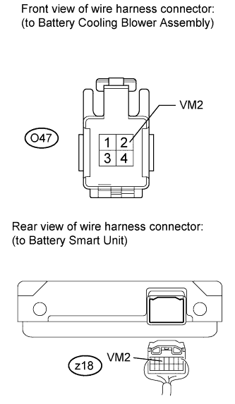 |
Measure the resistance according to the value(s) in the table below.
| Tester Connection | Switch Condition | Specified Condition |
| O47-2 (VM2) - z18-5 (VM2) | Power switch off | Below 1 Ω |
| Tester Connection | Switch Condition | Specified Condition |
| O47-2 (VM2) or z18-5 (VM2) - Body ground | Power switch off | 10 kΩ or more |
|
| ||||
| OK | |
|
| 6.CHECK HARNESS AND CONNECTOR (BATTERY COOLING BLOWER ASSEMBLY - BODY GROUND) |
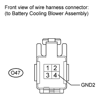 |
Measure the resistance according to the value(s) in the table below.
| Tester Connection | Switch Condition | Specified Condition |
| O47-4 (GND2) - Body ground | Power switch off | Below 1 Ω |
|
| ||||
| OK | |
|
| 7.CHECK HARNESS AND CONNECTOR (BATTERY COOLING BLOWER - HYBRID VEHICLE CONTROL ECU) |
Disconnect the D36 connector from the hybrid vehicle control ECU (Click here).
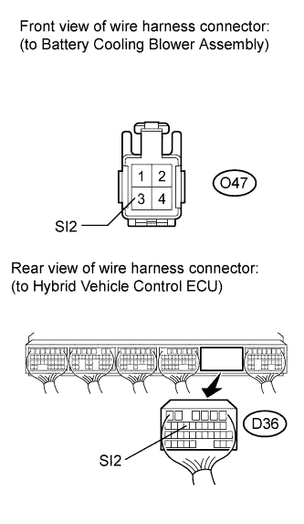 |
Measure the resistance according to the value(s) in the table below.
| Tester Connection | Switch Condition | Specified Condition |
| O47-3 (SI2) - D36-13 (SI2) | Power switch off | Below 1 Ω |
| Tester Connection | Switch Condition | Specified Condition |
| O47-3 (SI2) or D36-13 (SI2) - Body ground | Power switch off | 10 kΩ or more |
|
| ||||
| OK | |
|
| 8.INSPECT HYBRID VEHICLE CONTROL ECU |
Install the battery cover.
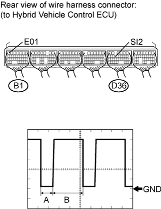 |
Using an oscilloscope, measure the waveform according to the condition in the table below.
| Item | Contents |
| Terminal | D36-13 (SI2) - B1-7 (E01) |
| Equipment Setting | 1 V/DIV, 50 μs/DIV |
| Condition | Power switch on (IG or READY) |
|
| ||||
| OK | ||
 | ||
| ||
| 9.CHECK FUSE (BATT FAN) |
Remove the BATT FAN fuse.
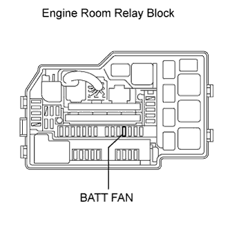 |
Measure the resistance of the BATT FAN fuse.
| Tester Connection | Condition | Specified Condition |
| BATT FAN fuse | Always | Below 1 Ω |
|
| ||||
| OK | |
|
| 10.CHECK RELAY (BATT FAN) |
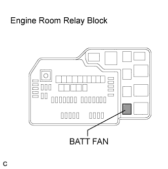 |
Remove the BATT FAN relay.
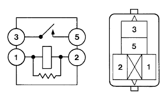 |
Measure the resistance according to the value(s) in the table below.
| Tester Connection | Condition | Specified Condition |
| 1-2 | Always | 130 to 235 Ω |
| 3-5 | Auxiliary battery voltage is not applied between terminals 1 and 2 | 10 kΩ or more |
| Auxiliary battery voltage is applied between terminals 1 and 2 | Below 1 Ω |
|
| ||||
| OK | |
|
| 11.CHECK HARNESS AND CONNECTOR (BATT FAN RELAY - BATT FAN FUSE) |
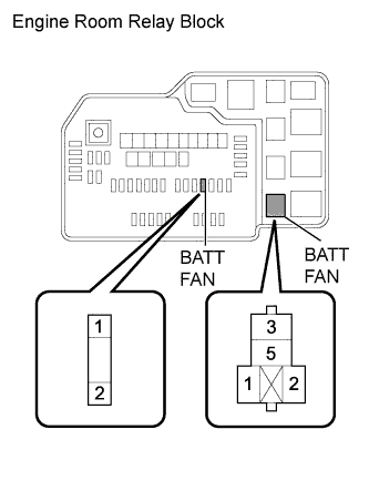 |
Measure the resistance according to the value(s) in the table below.
| Tester Connection | Switch Condition | Specified Condition |
| BATT FAN fuse terminal 1 - BATT FAN relay terminal 1 | Power switch off | Below 1 Ω |
| BATT FAN fuse terminal 1 - BATT FAN relay terminal 3 | Below 1 Ω |
|
| ||||
| OK | |
|
| 12.CHECK HARNESS AND CONNECTOR (BATT FAN RELAY - BATTERY COOLING BLOWER ASSEMBLY) |
Disconnect the O47 battery cooling blower assembly connector (Click here).
|
Measure the resistance according to the value(s) in the table below.
| Tester Connection | Switch Condition | Specified Condition |
| BATT FAN relay terminal 5 - O47-1 (IG2) | Power switch off | Below 1 Ω |
|
| ||||
| OK | |
|
| 13.CHECK HARNESS AND CONNECTOR (BATT FAN RELAY - HYBRID VEHICLE CONTROL ECU) |
Disconnect the A43 connector from the hybrid vehicle control ECU (Click here).
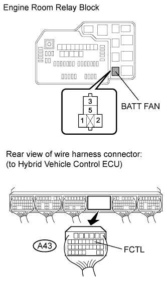 |
Measure the resistance according to the value(s) in the table below.
| Tester Connection | Switch Condition | Specified Condition |
| BATT FAN relay terminal 2 - A43-9 (FCTL) | Power switch off | Below 1 Ω |
| Tester Connection | Switch Condition | Specified Condition |
| BATT FAN relay terminal 2 or H43-9 (FCTL) - Body ground | Power switch off | 10 kΩ or higher |
|
| ||||
| OK | ||
| ||
| ||
| 14.CHECK HARNESS AND CONNECTOR (BATT FAN FUSE - BATT FAN RELAY) |
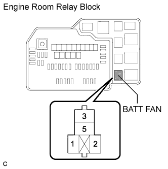 |
Remove the BATT FAN relay from the engine room J/B.
Measure the resistance according to the value(s) in the table below.
| Tester Connection | Switch Condition | Specified Condition |
| BATT FAN relay terminal 3 - Body ground | Power switch off | 10 kΩ or higher |
|
| ||||
| OK | |
|
| 15.CHECK HARNESS AND CONNECTOR (BATT FAN RELAY - BATTERY COOLING BLOWER ASSEMBLY) |
Disconnect each of the 3 battery cooling blower assembly connectors (Click here).
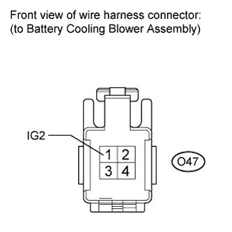 |
Measure the resistance according to the value(s) in the table below.
| Tester Connection | Switch Condition | Specified Condition |
| O47-1 (IG2) - Body ground | Power switch off | 10 kΩ or higher |
|
| ||||
| OK | |
|
| 16.INSPECT BATTERY COOLING BLOWER ASSEMBLY |
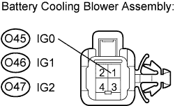 |
Measure the resistance according to the value(s) in the table below.
| Tester Connection | Switch Condition | Specified Condition |
| O45-1 (IG0) - Body ground | Power switch off | 10 kΩ or higher |
| O46-1 (IG1) - Body ground | Power switch off | 10 kΩ or higher |
| O47-1 (IG2) - Body ground | Power switch off | 10 kΩ or higher |
| NEXT | |
|
| 17.REPLACE BATTERY COOLING BLOWER ASSEMBLY |
Replace the defective battery cooling blower assembly (Click here).
| NEXT | ||
| ||
| ||
| 18.REPAIR OR REPLACE HARNESS OR CONNECTOR |
| NEXT | ||
| ||
| ||
