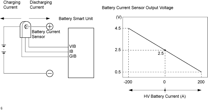
DTC P0ABF-123 Hybrid Battery Pack Current Sensor Circuit |
| DTC No. | DTC Detection Condition | Trouble Area |
| P0ABF-123 | When the battery current sensor is abnormal (1 trip detection) |
|
| Related DTCs | P0ABF-123 |
| Required sensors/components | Battery current sensor |
| Frequency of operation | Continuous |
| Duration | TOYOTA's intellectual property |
| MIL operation | Immediately |
| Sequence of operation | None |
| The monitor will run whenever the DTCs listed are not present | TOYOTA's intellectual property |
| TOYOTA's intellectual property | - |
| Battery smart unit | P0ABF-123 is not detected |
| 1.CHECK DTC OUTPUT (DTC P0A1F-123 IS OUTPUT) |
Connect the Techstream to the DLC3.
Turn the power switch on (IG).
Select the following menu items: Powertrain / Hybrid Control / Trouble Codes.
Read output DTCs (Click here).
| Result | Proceed to |
| P0A1F-123 is not output. | A |
| P0A1F-123 is also output. | B |
|
| ||||
| A | |
 |
| 2.INSPECT BATTERY SMART UNIT |
Connect the z18 battery smart unit connector (Click here).
Turn the power switch on (IG).
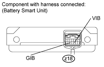 |
Measure the voltage according to the value(s) in the table below.
| Tester Connection | Switch Condition | Specified Condition |
| z18-10 (VIB) - z18-12 (GIB) | Power switch on (IG) | 4.6 to 5.4 V |
Reconnect the battery smart unit connector.
|
| ||||
| OK | |
|
| 3.CHECK HV BATTERY (BATTERY TEMPERATURE SENSOR) |
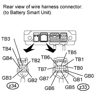 |
Disconnect the z33 and z34 connectors from the battery smart unit.
Measure the resistance according to the conditions and value(s) in the tables below.
| Tester Connection | Thermistor No. |
| z33-1 (TB0) - z33-6 (GB0) | 0 |
| z33-2 (TB1) - z33-7 (GB1) | 1 |
| z34-1 (TB2) - z34-4 (GB2) | 2 |
| z34-2 (TB3) - z34-5 (GB3) | 3 |
| z34-3 (TB4) - z34-6 (GB4) | 4 |
| z33-3 (TB5) - z33-8 (GB5) | 5 |
| z33-4 (TB6) - z33-9 (GB6) | 6 |
| z33-5 (TB7) - z33-10 (GB7) | 7 |
| Thermistor Temperature | Switch Condition | Specified Condition (kΩ) |
| 32°F (0°C) | Power switch off | 27.0 to 27.6 |
| 77°F (25°C) | Power switch off | 9.9 to 10.1 |
| 104°F (40°C) | Power switch off | 5.77 to 5.89 |
Disconnect the z18 connector from the battery smart unit.
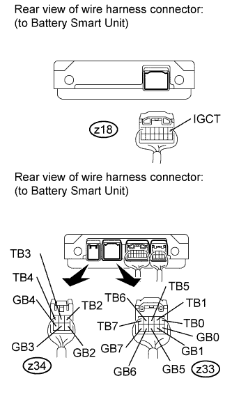 |
Measure the resistance according to the conditions and value(s) in the tables below.
| Tester Connection | Switch Condition | Standard resistance |
| z33-1 (TB0) - z18-1 (IGCT) | Power switch off | 10 kΩ or more |
| z33-2 (TB1) - z18-1 (IGCT) | Power switch off | 10 kΩ or more |
| z34-1 (TB2) - z18-1 (IGCT) | Power switch off | 10 kΩ or more |
| z34-2 (TB3) - z18-1 (IGCT) | Power switch off | 10 kΩ or more |
| z34-3 (TB4) - z18-1 (IGCT) | Power switch off | 10 kΩ or more |
| z33-3 (TB5) - z18-1 (IGCT) | Power switch off | 10 kΩ or more |
| z33-4 (TB6) - z18-1 (IGCT) | Power switch off | 10 kΩ or more |
| z33-5 (TB7) - z18-1 (IGCT) | Power switch off | 10 kΩ or more |
| z33-6 (GB0) - z18-1 (IGCT) | Power switch off | 10 kΩ or more |
| z33-7 (GB1) - z18-1 (IGCT) | Power switch off | 10 kΩ or more |
| z34-4 (GB2) - z18-1 (IGCT) | Power switch off | 10 kΩ or more |
| z34-5 (GB3) - z18-1 (IGCT) | Power switch off | 10 kΩ or more |
| z34-6 (GB4) - z18-1 (IGCT) | Power switch off | 10 kΩ or more |
| z33-8 (GB5) - z18-1 (IGCT) | Power switch off | 10 kΩ or more |
| z33-9 (GB6) - z18-1 (IGCT) | Power switch off | 10 kΩ or more |
| z33-10 (GB7) - z18-1 (IGCT) | Power switch off | 10 kΩ or more |
|
| ||||
| OK | ||
 | ||
| ||
| 4.INSPECT BATTERY SMART UNIT |
Disconnect the z19 battery current sensor connector from the HV relay assembly (Click here).
Turn the power switch on (IG).
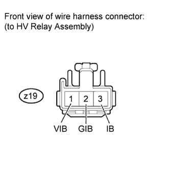 |
Measure the voltage according to the value(s) in the table below.
| Tester Connection | Switch Condition | Specified Condition |
| z19-1 (VIB) - z19-2 (GIB) | Power switch on (IG) | 4.6 to 5.4 V |
|
| ||||
| OK | ||
| ||
| ||
| 5.CHECK BATTERY PACK WIRE (BATTERY SMART UNIT - BATTERY CURRENT SENSOR) |
Remove the service plug grip.
Remove the battery cover.
Disconnect the z18 connector from the battery smart unit.
Disconnect the z19 HV relay assembly (battery current sensor) connector.
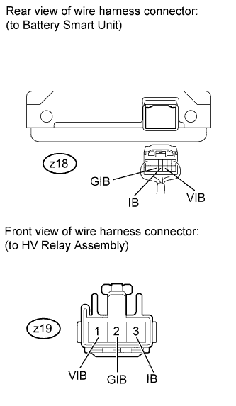 |
Measure the resistance according to the value(s) in the table below.
| Tester Connection | Switch Condition | Specified Condition |
| z18-11 (IB) - z19-3 (IB) | Power switch off | Below 1 Ω |
| z18-12 (GIB) - z19-2 (GIB) | Power switch off | Below 1 Ω |
| z18-10 (VIB) - z19-1 (VIB) | Power switch off | Below 1 Ω |
| Tester Connection | Switch Condition | Specified Condition |
| z18-11 (IB) or z19-3 (IB) - Body ground and other terminals | Power switch off | 10 kΩ or higher |
| z18-12 (GIB) or z19-2 (GIB) - Body ground and other terminals | Power switch off | 10 kΩ or higher |
| z18-10 (VIB) or z19-1 (VIB) - Body ground and other terminals | Power switch off | 10 kΩ or higher |
|
| ||||
| OK | ||
| ||
| ||

