Home › BRAKE › BRAKE CONTROL › FRONT SPEED SENSOR

FRONT SPEED SENSOR > REMOVAL

for Preparation Click here


HINT:
  1. Use the same procedure for the LH side and RH side.
  2. The following procedure is for the LH side.
  3. If the sensor rotor needs to be replaced, replace it together with the front drive outboard joint shaft assembly (Click here).


1. DISCONNECT CABLE FROM NEGATIVE BATTERY TERMINAL

NOTICE:
When disconnecting the cable, some systems need to be initialized after the cable is reconnected (Click here).


2. REMOVE SERVICE PLUG GRIP

CAUTION:
  1. Remove the service plug to interrupt a high voltage circuit at the time of the check.
  2. Keep the removed service plug in your pocket to prevent other technicians from accidentally reconnecting it while you are servicing the vehicle.
  3. All the high voltage wiring connectors are colored in orange.


    A175634
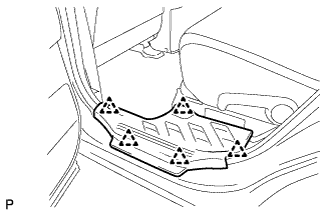
  1. Remove the 5 clips and door scuff plate LH.


    A175635
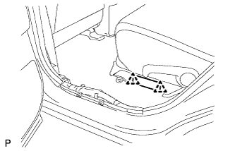
  1. Remove the 2 clips and reclining hinge cover.


    A175636
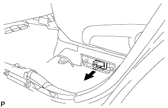
  1. Wear insulated glove and remove the service plug grip, after sliding up the lever of the service plug grip.

    CAUTION:
    1. Keep the removed service plug in your pocket to prevent other technicians from accidentally reconnecting it while you are servicing the vehicle.
    2. After removing the service plug grip, do not touch the high voltage connectors and terminals for 5 minutes.

    NOTICE:
    After removing the service plug grip, do not operate the power switch as it may damage the hybrid vehicle control ECU.


3. REMOVE FRONT WHEEL


4. REMOVE NO. 1 ENGINE UNDER COVER


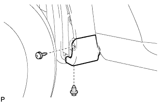
5. REMOVE FRONT FENDER MOULDING SUB-ASSEMBLY LH


    B172795
  1. Remove the clip.

  1. Using a 4 mm hexagon wrench, remove the screw.


    B172796
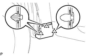
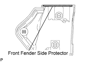
  1. Peel off the front fender side protector and disengage the 3 clips, and then remove the front fender moulding sub-assembly.
  1. Remove the pad from the front fender moulding sub-assembly.

  1. Remove the 2 No. 4 clips from the front fender moulding sub-assembly.


    B172797E01
  1. Remove the front fender side protector from the front fender moulding sub-assembly.


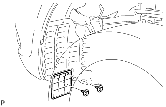
6. REMOVE FRONT WHEEL OPENING EXTENSION PAD


    B174748
  1. Remove the 2 screws and front wheel opening extension pad.


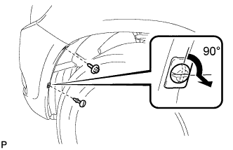
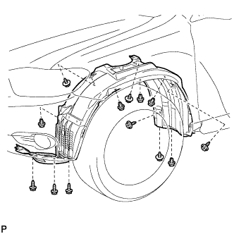
7. REMOVE FRONT FENDER LINER


    B175996E01
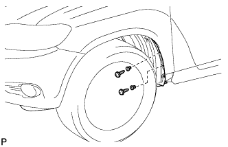
  1. Remove the screw.

  1. Using a screwdriver, turn the pin 90 degrees and remove the pin hold clip.


    B174749
  1. Using a 4 mm hexagon wrench, remove the 2 screws.

  1. Remove the 2 grommets.

    HINT:
    The grommets need to be replaced with new ones because they will break when they are removed.


    B174751
  1. Remove the 5 clips, 8 screws and front fender liner LH.


8. REMOVE FRONT SPEED SENSOR


    C165817
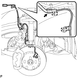
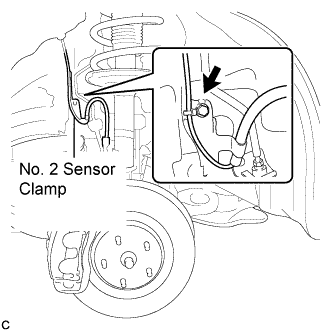
  1. Disconnect the front speed sensor connector and remove the 2 clamps.


    C165805E01
  1. Remove the bolt and No. 2 sensor clamp from the body.


    C165808E01
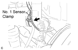
  1. Remove the bolt, No. 1 sensor clamp, and flexible hose as a set from the shock absorber assembly.


    C165818E02
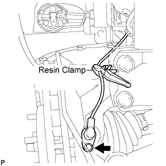
  1. Remove the bolt, resin clamp, and the front speed sensor.

    NOTICE:
    1. Prevent foreign matter from attaching to the front speed sensor tip.
    2. Clean the sensor installation hole and contact surface every time the sensor is removed.